Removal and Inst a l l a t i on Procedures
6-- 26
TDS5000B Series Se r vi c e Manual
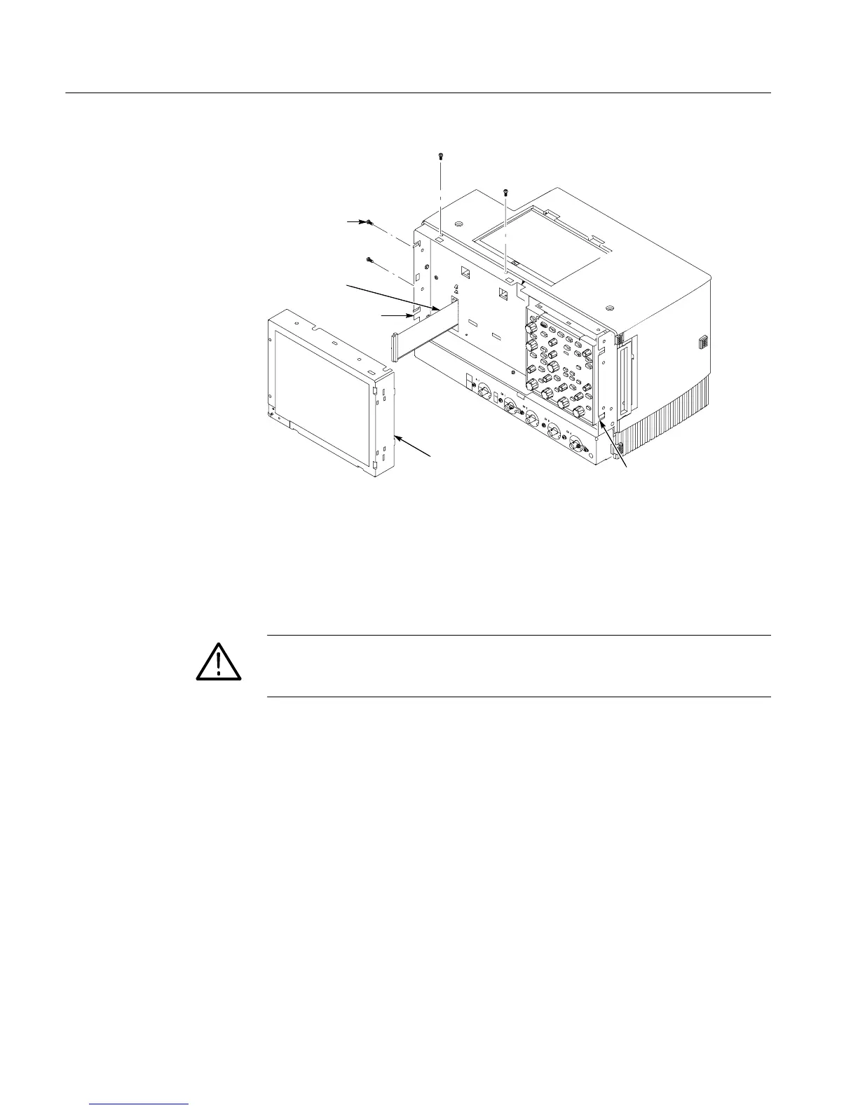
T-15 TORX
drive screw (4)
Display
assembly
J5 Flex cable
Finger relief
Finger relief
Finger reliefFinger relief
Figure 6--11: Display removal
4. Remove the Touch panel from the Display assembly: See figures 6--12 and
6-- 13, on pages 6--27 and 6--28.
CAUTION. To prevent degradation of the display sharpness, this procedure must
be performed in a dust free environment. Wear cot t on gloves to prevent finger
oils from contaminating any surfaces of the display glass.
a. Disconnect cables J1 and J7 from the Display Adapter circuit board.
b. Se pa r a t e the assembly by carefully prying the (outer) Touch panel
assembly from the (inner) Display assembly. Insert a flat-bladed
screwdriver in the access notches to push out on t he Touch panel
assembly.

 Loading...


