Removal and Inst a l l a t i on Procedures
TDS5000B Series Se r vi c e Manual
6-- 27
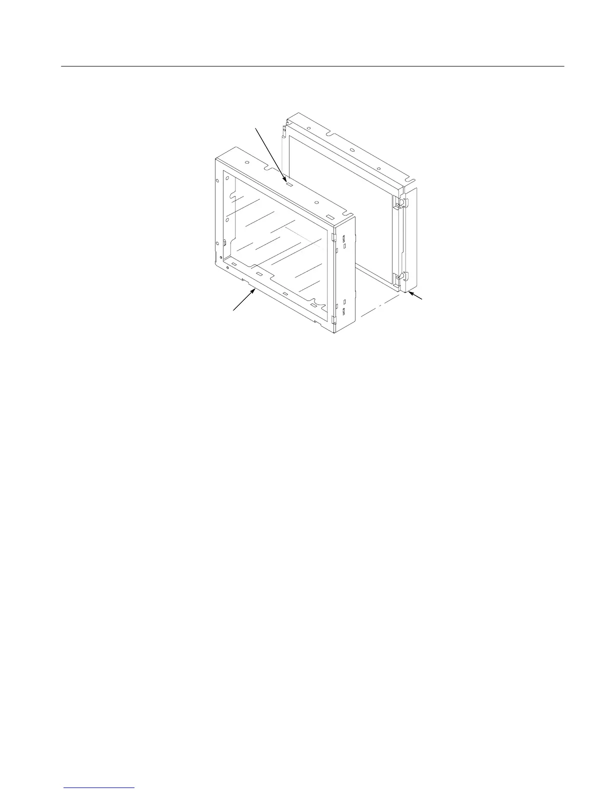
Touch panel
LCD module
Access not c hes
(top and bottom)
Figure 6--12: Touch panel and Display as s e mbly removal
5. Reinstallation: Do in reverse st e ps 1 through 5 to reinst a l l the Display
assembly.
1. Locate module to be removed: Locate the display adapter board in t he loca t or
diagram Internal Modules, Figure 6--7, on pa ge 6--19. Additional modules to
be Removed:
! Trim (front panel & top)
! Display assembly
2. Remove the Display Adapter Board: See Figure 6--13, pages 6--28.
a. Disconnect cables J1, J6, J5, and J7 fr om the Display Adapter board.
b. Sl i de the connector clip, if present, off of J4.
c. Disconne c t cable J4 from the Display Adapter board.
d. Re m ove the three T-15 TORX drive screws t ha t secure the Display
Adapter circuit board to t he Display assembl y. Remove the Displ a y
Adapter from the assembly.
3. Reinstallation: Do in reverse st e ps a through d to reinst a l l the board.
Display Adapter Board

 Loading...


