Removal and Inst a l l a t i on Procedures
6-- 32
TDS5000B Series Se r vi c e Manual
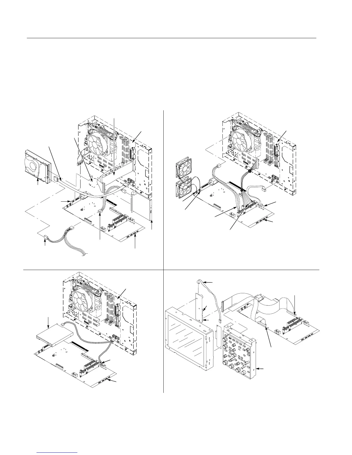
PC Interface Board and Motherboard Cable Connections
Figure 6--17 shows the location of cables and cable conne c t or s for the PC
interface board and the m ot he r boa r d. Pay close attention to this diagram and the
cable connections when you disassem bl e and reassembl e the instrument .
J1040/Power
supply cable
J1401/CPU
power cable
J520/ATX
USB cable
J1060
J1070
PC interface
board
CDRW
drive
Hard drive
PC interface
board
Motherboard
J510/CDRW drive
power cable
From power
supply
J510/CDRW drive
power cable
Front panel
assembly
J510/Front panel
PWR cable
J2
J3
J1010/Front
panel cable
Inverter
adapter cable
J1000/Dual
USB cable
Floppy disk
drive
Motherboard
PC interface
board
Motherboard
GPIB
J1600
CDRW and HD cables
HD cable
(SN B029999 and below)
(SN B030000 and above)
Figure 6--17: PC Interface board and motherboard cable connections

 Loading...


