Removal and Inst a l l a t i on Procedures
6-- 24
TDS5000B Series Se r vi c e Manual
1. Locate module to be removed: Loca t e the Front Panel assembly in Fig-
ure 6--8, on page 6--22. Additional modules to be removed:
! Front Panel Knobs
! Trim (front panel )
! Front Panel asse m bl y
! Front Panel Boar d
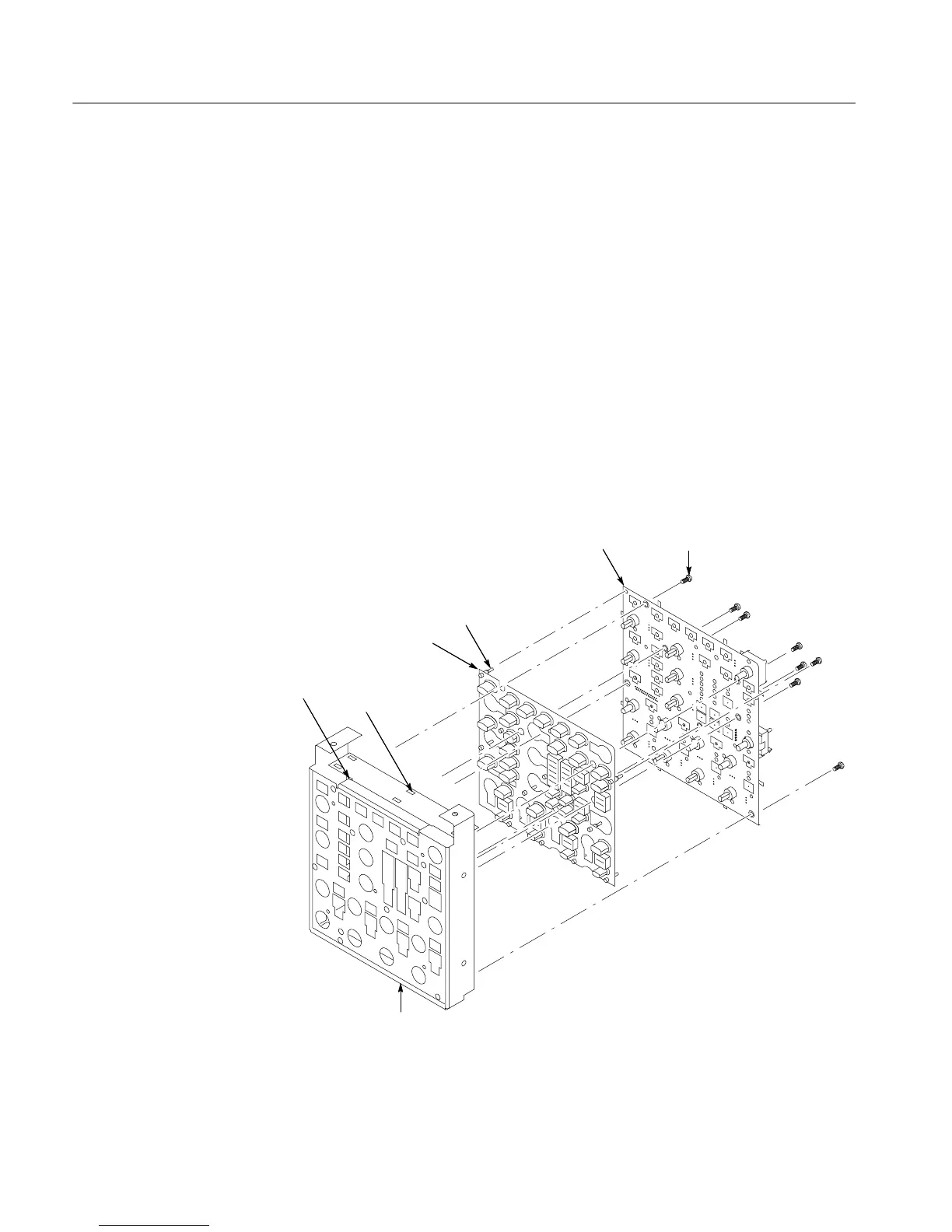
2. Remove the Front Panel keypad: See Figure 6--10.
a. Pull on each of the keypad support gui de s to separate the keypad from
the Front Panel board. Use a pair of tweezers or equivalent tool to pull
the twelve ke ypa d support guides.
b. Re m ove the keypad from the Front Panel board.
T-15 TORX
screw (8)
Pry point
access hole
Alignment
stud
Pry point access hole
Keypad support
guide (12)
Front panel board
Keypad
Figure 6--10: Front panel board and keyboard removal
Front Panel K e y pa d

 Loading...


