Removal and Inst a l l a t i on Procedures
TDS5000B Series Se r vi c e Manual
6-- 23
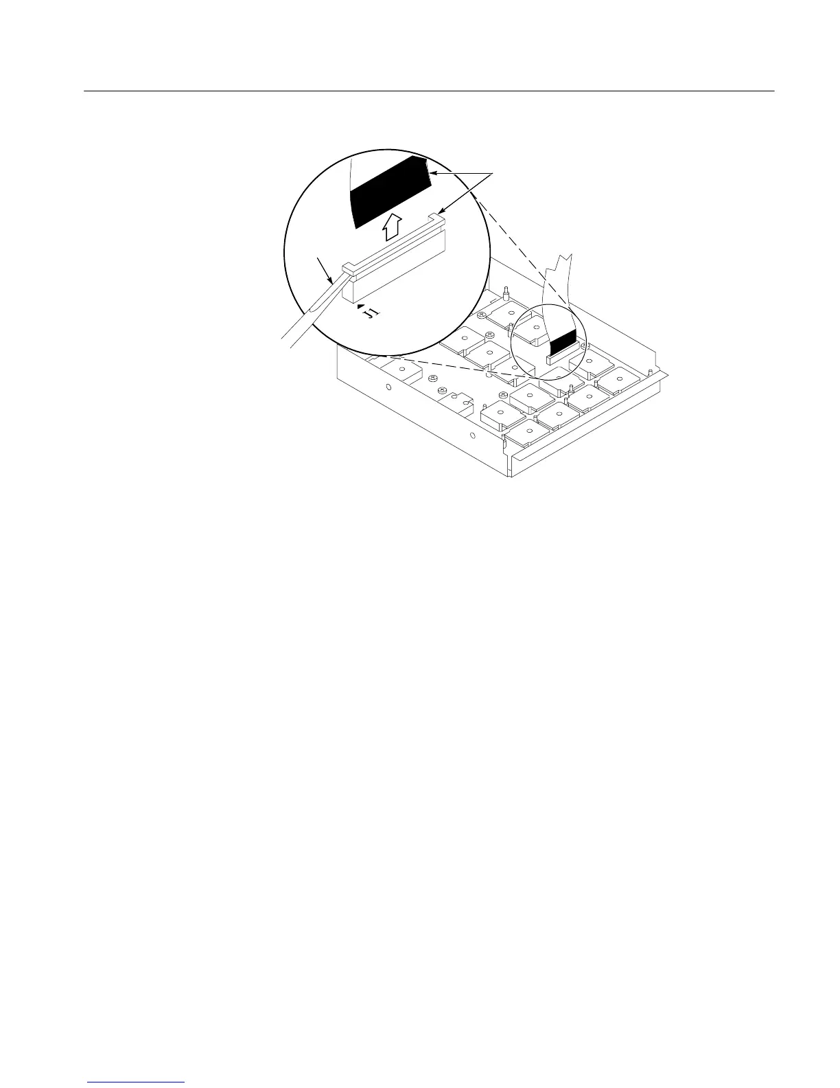
Screwdriver
Black stripe
toward connector
Figure 6--9: J1 flex c a bl e connector removal
1. Locate module to be removed: Loca t e the Front Panel assembly Figure 6-- 8,
page 6--22. Additional modules to be removed:
! Front Panel Knobs
! Trim (front panel )
! Front Panel asse m bl y
2. Remove the F ront Panel board: See Figur e 6--10, page 6-- 24.
a. Remove the ei ght T-15 TORX drive screws that secure the Front Panel
board to the Front Panel assembly.
b. Pr y the board up off the alignment studs. Place a flat-bladed screwdriver
in the pry-point access holes to pry the board up from the assembly.
c. Remove the board from the assembly.
3. Reinstallation: Do in reverse st e ps a through c to rei nst a l l the Front Panel
board.
Front Panel B oa r d

 Loading...


