Removal and Inst a l l a t i on Procedures
TDS5000B Series Se r vi c e Manual
6-- 29
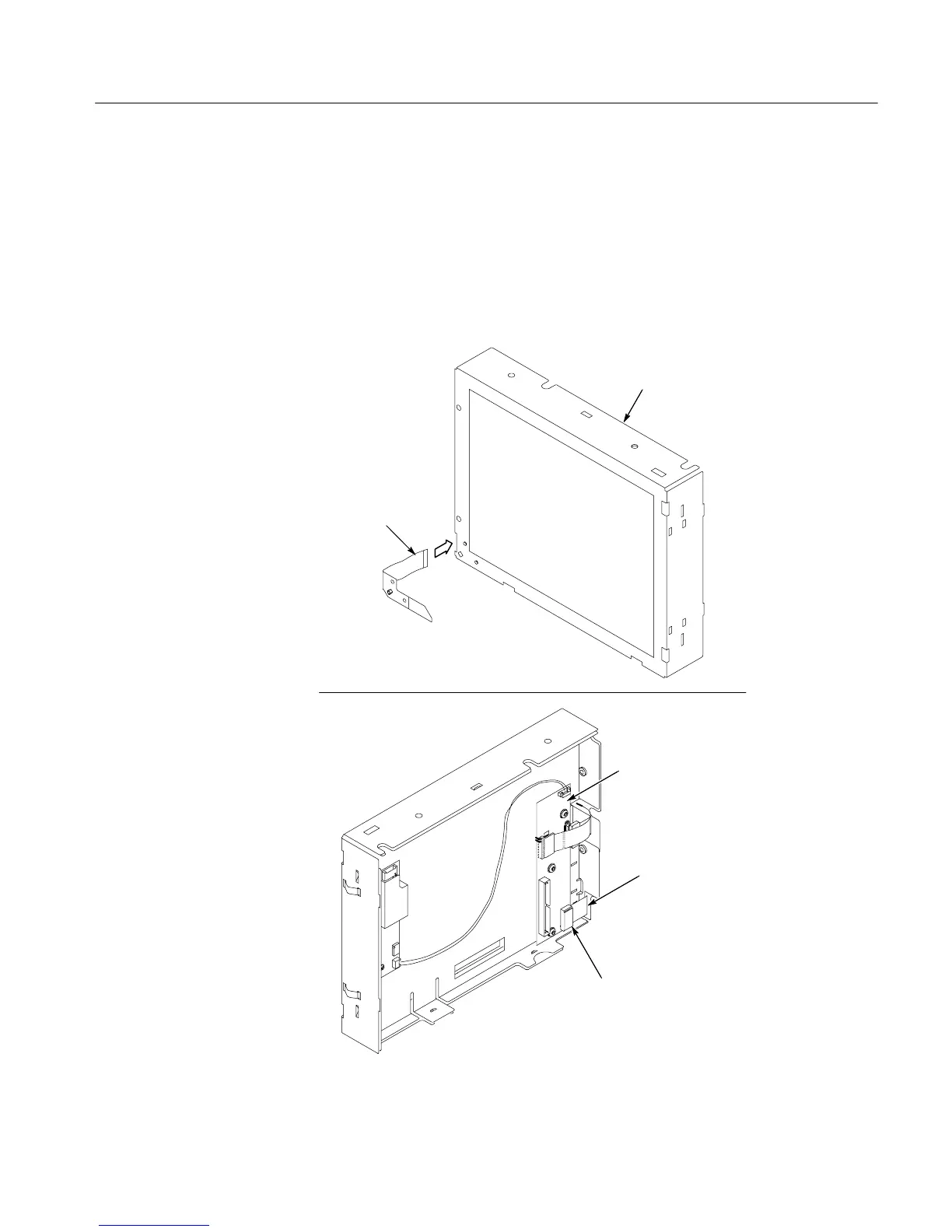
b. Sl i de the connector end of the power f l e x circuit through the slot in the
Display assembly. Make sure the flex circuit connector aligns with J7 on
the Display Adapter circuit board.
c. Align the holes in the power flex ci r c ui t to the two index post s on the
front side of the Display assembly.
d. Fi r m l y press the flex circuit to the Display assembly chassis surface.
Display
assembly
Display adapter board
J7
Front view
Back view
Power flex circuit
Power flex circuit
Figure 6--14: Power flex c i rc uit removal

 Loading...


