Removal and Inst a l l a t i on Procedures
TDS5000B Series Se r vi c e Manual
6-- 45
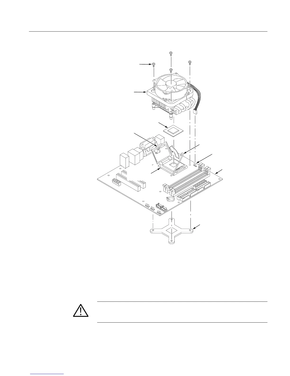
Motherboard
Fan and heatsink
Microprocessor
Cover
Locking lev er
securing pin
Heatsink retaining
screws (4)
J1F1 power cable
Locking lev er
Mounting bracket
Figure 6--25: Heatsink fan and microprocessor removal
1. Locate module to be removed: Locate the PC interface board in the locator
diagram Internal Modules, Figure 6--7, on pa ge 6--19. Note the location of
cables and c a bl e connectors see Figure 6--17 on page 6--32.
CAUTION. Before install i ng the PC interface board, fully install the acquisition
board. Doing this helps ensure correct ali gnme nt of the 125-pin connector
between the ac qui si t i on board and the PC interface board.
Additional modules to be remove d:
PC Interface Board

 Loading...


