Removal and Inst a l l a t i on Procedures
6-- 10
TDS5000B Series Se r vi c e Manual
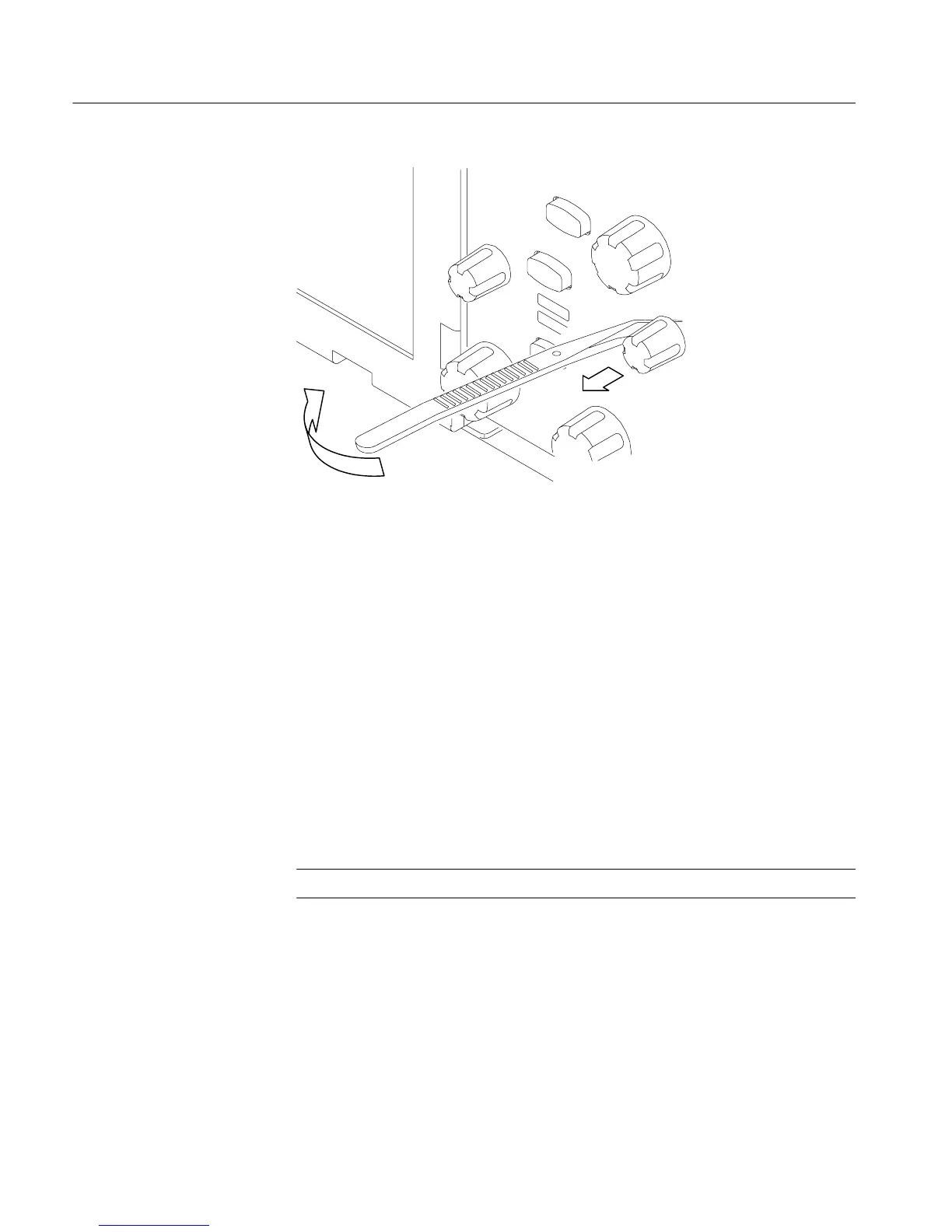
Figure 6--1: Knob removal
1. Locate module to be removed: Loca t e the Trim in the locator diagram. See
Figure 6--2, page 6--13.
2. Remove the c arry i ng handle and the left side panel: Use Figure 6--2, page
6-- 13 as a guide.
a. Remove the two T-15 TORX drive screws that secure the handle to the
oscilloscope. Remove the handle from the osci l l osc ope .
b. Re m ove the two T-15 TORX drive screws from the bottom of the left
side panel.
c. Slide the left side panel towards the rear of the oscilloscope allowing the
tabs to cle a r the cover openings, then pull out to remove the panel from
the oscilloscope.
NOTE. For many service operations you do not need to remove the left panel.
3. Remove the ri ght side panel: Use Figure 6--2, page 6--13 as a guide.
a. Remove the CDRW Drive trim by inserting a flat blade screwdriver in
the bottom slot of the CDRW trim a nd gentl y prying the trim piece out of
the side panel . Pull the trim up and out from the oscilloscope.
b. Re m ove the two T-15 TORX drive screws from the bottom of the
oscilloscope that secure the right side pane l .
Trim and Carrying Handle

 Loading...


