Removal and Inst a l l a t i on Procedures
6-- 30
TDS5000B Series Se r vi c e Manual
1. Locate modules t o be removed: Loca t e the Floppy Disk Drive in the locat or
diagram Internal Modules, Figure 6--7, page 6-- 19. Additional modules to be
removed:
! Trim (front panel )
! Cover (top)
2. Orient the osci l l osc ope : Set the oscilloscope so the bottom i s down on the
work surface a nd the front panel is facing you.
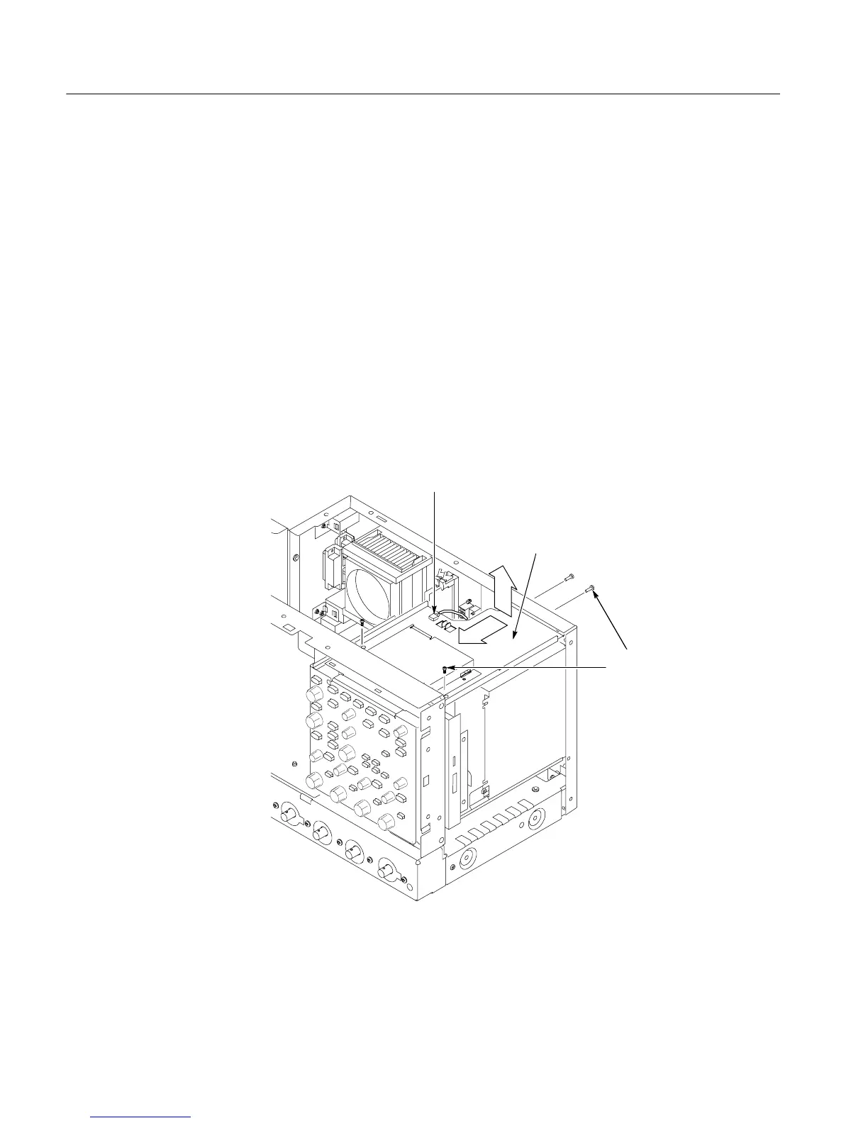
3. Remove the f l oppy disk drive: Use Figure 6--15 as a guide. A #0 Phillips
screwdriver is required for this procedure.
a. Remove the ca bl e from the back of the floppy disk drive.
b. Re m ove the two T-15 TORX drive screws that secure the floppy disk
drive assembly to the chassis.
After the screws remove pull the floppy
assembly forward 0. 500 in then lift up
away from the back panel.
Floppy drive cable
T-15
TORX
screw (4)
Figure 6--15: Floppy disk dri v e assembly removal
c. Remove the two small Phillips screws that secure the floppy disk dri ve
assembly to the bracket.
Floppy Disk Drive

 Loading...


