Removal and Inst a l l a t i on Procedures
6-- 40
TDS5000B Series Se r vi c e Manual
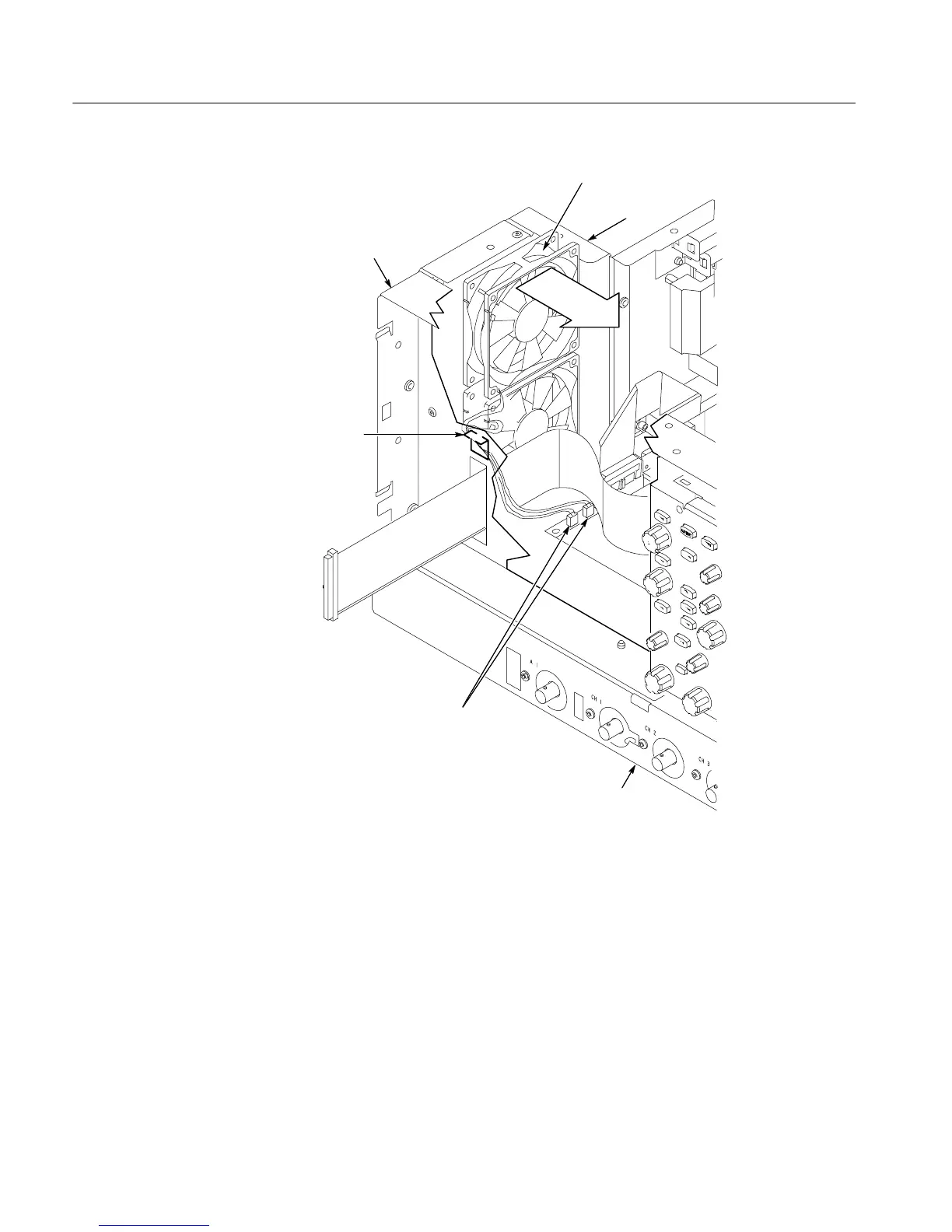
Fans
Fan cable
holder
Left side of the
instrument
Front of the
instrument
Back of the
instrument
Disconnect fan cables
Figure 6--22: Disconne c t i ng the fan cables
1. Assemble equipment and locate module s to be removed: Locate the modules
to be removed in the locator diagram Internal Modules, Fi gur e 6--7,
on page 6--19. Additional modules to be removed:
! Trim (all)
! Right side cover
2. Orient the osci l l osc ope : Set the oscilloscope so the bottom i s down on the
work surface a nd the back is facing you.
Power Supply

 Loading...


