Removal and Inst a l l a t i on Procedures
TDS5000B Series Se r vi c e Manual
6-- 37
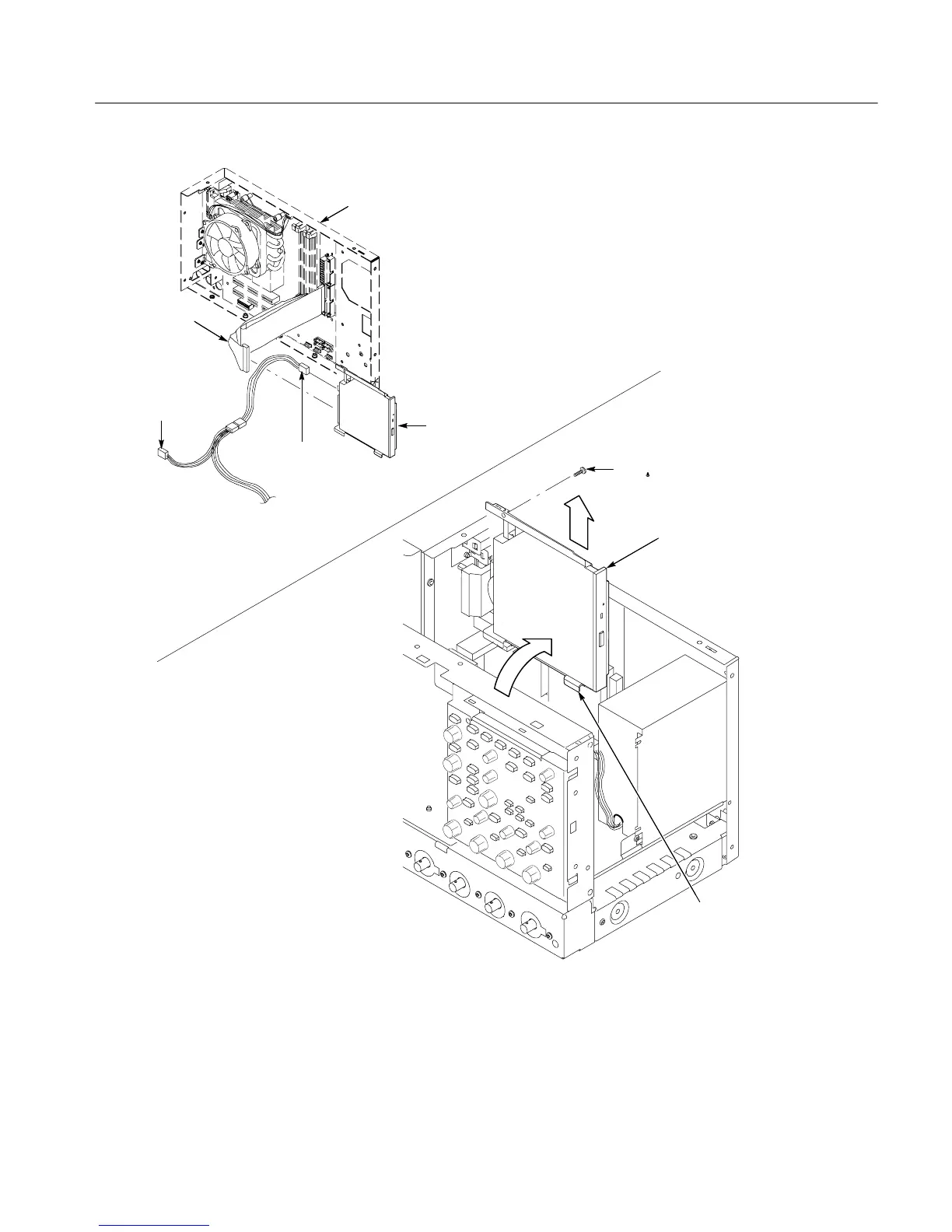
CDRW drive
assembly
T-15 TORX
drive screw (1)
Tab (2)
From power
supply
Disconnect from
the CDRW drive
assembly
Disconnect from
the CDRW drive
assembly
To hard
drive
Motherboard
assembly
CDRW drive
assembly
Figure 6--20: CDRW drive assembly removal
1. Locate module to be re mov e d: Locate the fans in the locator diagram Internal
Modules, Figure 6--7, page 6-- 19. Additional modules to be removed:
! Trim (all exce pt front panel and acquisition)
Fan Removal

 Loading...


