Troubleshooting
TDS5000B Series Se r vi c e Manual
6-- 55
If the instr um e nt will not power on, you can isolate the problem by observing the
specific symptoms and comparing them to those listed below.
If the mai ns power cord is connected and the osc i l l osc ope is not on, (power
supply is in standby mode), +5 V will be present on pin 9 of P1, the power
supply connector. If +5 V is not present, replace the power supply.
If the PSON signal on J1100, pin 2 is low, the osci l l osc ope interprets this signal
as an indica t i on that the power is on. If the PSON signal is high, measur e the
resistance from J510, pin 50 to ground, and J520, pin 6 to ground, while
depressing the ON/ ST BY button on the front panel. If the resistance m e a sur e s
less than 500 ohms in either test, replace the PC motherboard.
If the oscil l osc ope powers on momentarily, an ove r current condit i on exists.
Remove boards one at a time to locate a f a ul t (the display, disk drive adapt e r
board, acquisition board, and the PC motherboard). If you remove the PC
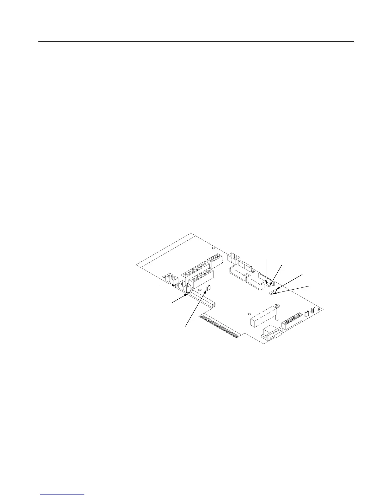
motherboard, you m ust jumper the forced power-on pins (see Figure 6--29). The
PC Interface board is requi r e d for power to come up.
If removing t he boards did not find the problem, r e pl a c e the power supply.
Reset button
TP1102
TP1103
JP1100 Forced
Power on
CR520
Hard disk
activity LED
CR710
PAI load
error LED
CR700
PAI loading
LED
Figure 6--29: Location of jumpe rs and reset button
Isolating to a Board if
Power Will Not Come Up

 Loading...


