100 Calibration 083730300A DCN8101
4.5.3 FLOW CALIBRATION
The flow calibration allows the user to adjust the values of the sample flow rates as they
appear in the Dashboard to match the actual flow rate measured at the sample inlet. This
does not change the hardware measurement of the flow sensors, only the software-
calculated values.
To carry out this adjustment, connect an external, sufficiently accurate flow meter to the
sample inlet per Section 5.6.4. Once the flow meter is attached and is measuring actual
gas flow, use the Utilities>Diagnostics>Flow Cal menu to input the flow meter reading
and calibrate.
4.6 CALIBRATION OF OPTIONAL SENSORS
This Section provides the calibration setup and procedures for the O
2
Sensor and the CO
2
Sensor options.
4.6.1 O
2
SENSOR CALIBRATION
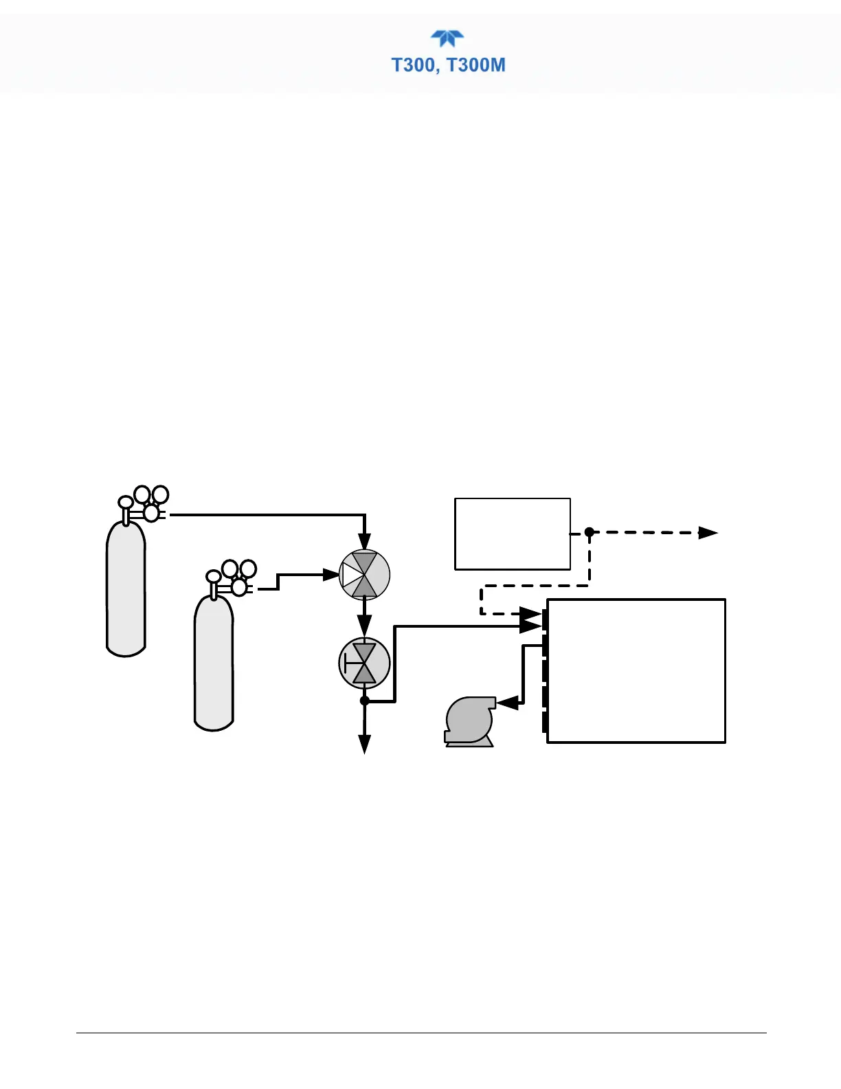
Set up the O
2
pneumatics connections as follows:
Calibrated N
2
at HIGH Span
Concentration
Calibrated O
2
at 20.8% Span
Concentration
Source of
SAMPLE GAS
Removed during
calibration
SAMPLE
EXHAUST
PUMP
VENT
3-way
Valve
Manual
Control Valve
VENT
here if input
is pressurized
Instrument
Chassis
Figure 4-4. O
2
Sensor Calibration Set Up
O
2
SENSOR ZERO GAS: Teledyne API recommends using pure N
2
when calibration
the zero point of your O
2
sensor option.
O
2
SENSOR SPAN GAS: Teledyne API recommends using 20.8% O
2
in N
2
when
calibration the span point of your O
2
sensor option (See Table 2-6).
In the Calibration>O2 menu, follow the steps in Section 4.2.1.2, this time setting the
expected O
2
span gas concentration. This should be equal to the percent concentration of
the O
2
span gas of the selected reporting range (default factory setting = 20.8%; the
approximate O
2
content of ambient air).