083730300A DCN8101 Getting Started 29
6. Each connector, J19 and J23, requires two shunts. Place one shunt on the two left-
most pins and the second shunt on the two pins next to it (see Figure 2-7).
7. Reattach the top case to the analyzer.
• The analyzer is now ready to have a voltage-sensing, recording device attached
to that output.
8. Calibrate the analog output in the Setup>Analog Outputs>Analog Output Cal menu.
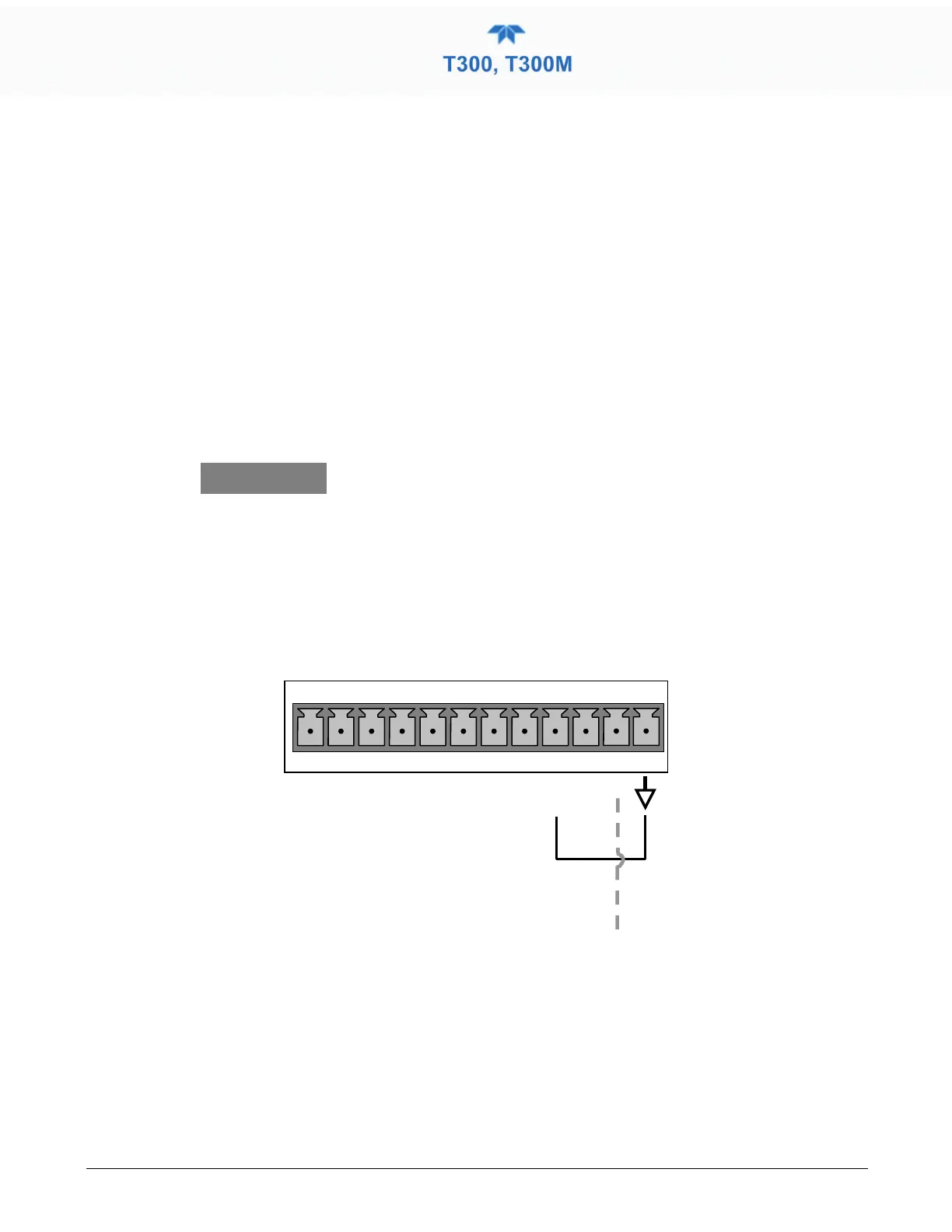
2.3.1.4 CONNECTING THE STATUS OUTPUTS (DIGITAL OUTPUTS)
The 12-pin STATUS connector allows the digital status outputs to report analyzer
conditions (configured through the Setup>Digital Outputs menu) via optically isolated
NPN transistors, which sink up to 50 mA of DC current. These outputs can be used to
interface with devices that accept logic-level digital inputs, such as Programmable Logic
Controllers (PLCs). Each status bit is an open collector output that can withstand up to
40 VDC. All of the emitters of these transistors are tied together and available at pin D
(see Figure 2-8).
ATTENTION
COULD DAMAGE INSTRUMENT AND VOID WARRANTY
Most PLCs have internal provisions for limiting the current
that the input will draw from an exter
nal device. When
connecting to a unit that does not have this feature, an
external dropping resistor must be used to limit the
current through the transistor output to less than 50 mA.
At 50 mA, the transistor will drop approximately 1.2V from
its collector to emitter.
Map the digital outputs 1 thru 8 through the
Setup>Digital Outputs menu.
Figure 2-8. Status Output Connector for Digital Outputs