083730300A DCN8101 Getting Started 33
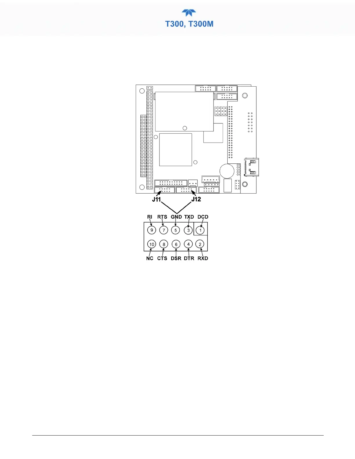
The signals from these two connectors are routed from the motherboard via a wiring
harness to two 10-pin connectors on the CPU card, J11 (COM1) and J12 (COM2)
(Figure 2-12).
Figure 2-12. Default Pin Assignments for CPU COM Port connector (RS-232)
RS-232 COM PORT DEFAULT SETTINGS
Received from the factory, the analyzer is set up to emulate a DCE or modem, with Pin 3
of the DB-9 connector designated for receiving data and Pin 2 designated for sending
data. (View these parameters in the Setup>Comm>COM1[COM2] menu).
• RS-232 (COM1): RS-232 (fixed) DB-9 male connector.
• Baud rate: 115200 bits per second (baud)
• Data Bits: 8 data bits with 1 stop bit
• Parity: None
• COM2: RS-232 (configurable to RS-485), DB-9 female connector.
• Baud rate: 19200 bits per second (baud)
• Data Bits: 8 data bits with 1 stop bit
• Parity: None