083730300A DCN8101 Getting Started 41
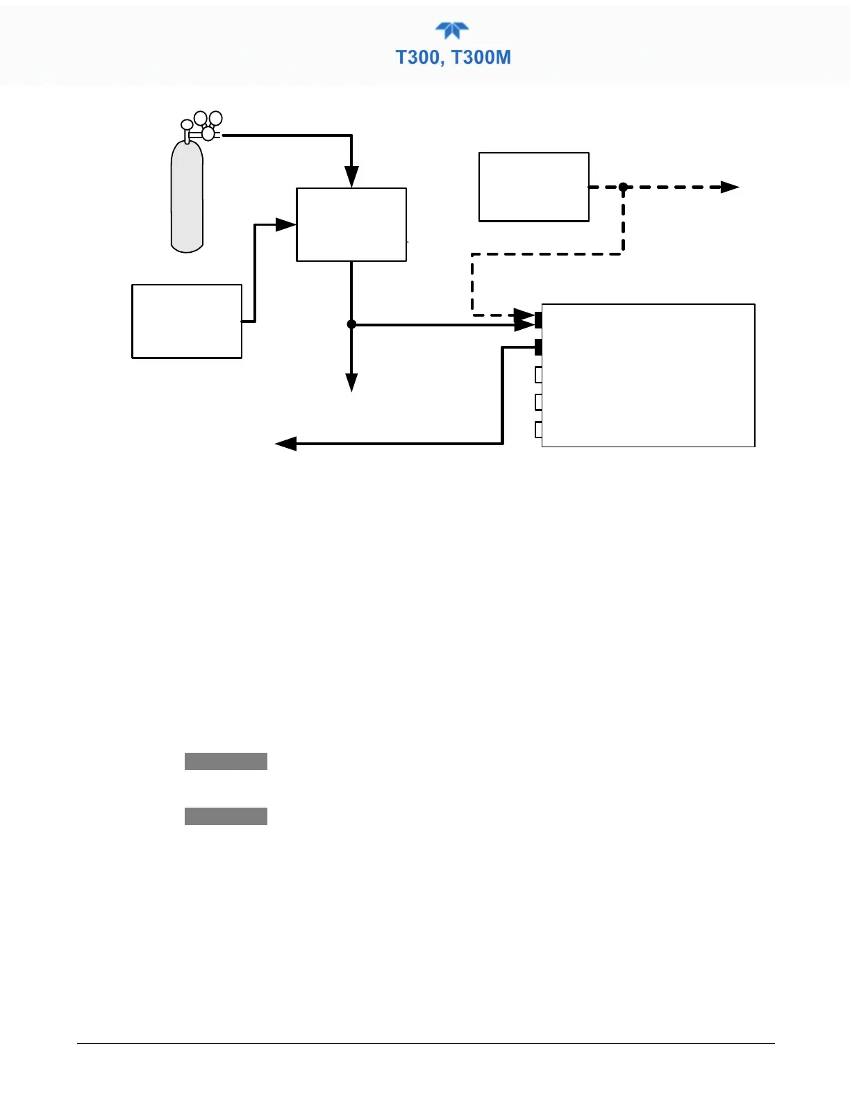
Source of
SAMPLE GAS
Removed during
calibration
VENT
MODEL 701
Zero Gas
Generator
Calibrated
CO Gas
at span gas
concentration
VENT
her e if input
is pressurized
SAMPLE
EXHAUST
Model 700 Gas
Dilution
Calibrator
Instrument
Chassis
Exhaust must be vented outside
of shelter or immediate area
sur rounding the instrument.
Figure 2-16. T300/T300M Pneumatic Connections – Basic Configuration Using Gas Dilution Calibrator
SAMPLE GAS SOURCE
Attach a sample inlet line to the SAMPLE inlet port. The sample input line should not
be more than 2 meters long.
• Maximum pressure of any gas at the sample inlet should not exceed 1.5 in-hg above
ambient pressure and ideally should equal ambient atmospheric pressure.
• In applications where the sample gas is received from a pressurized manifold, a vent must
be placed on the sample gas before it enters the analyzer.
CALIBRATION GAS SOURCES
The source of calibration gas is also attached to the SAMPLE inlet, but only when a
calibration operation is actually being performed.
Note T300M: EPA designation does not apply to this model.
Zero air and span gas inlets should supply their respective
gases in excess of the 800 cc3/min demand of the analyzer.
INPUT GAS VENTING
The span gas, zero air supply and sample gas line MUST be vented in order to ensure
that the gases input do not exceed the maximum inlet pressure of the analyzer as well as
to prevent back diffusion and pressure effects. These vents should be:
• At least 0.2m long;
• No more than 2m long and;
• Vented outside the shelter or immediate area surrounding the instrument.