083730300A DCN8101 Theory of Operation 157
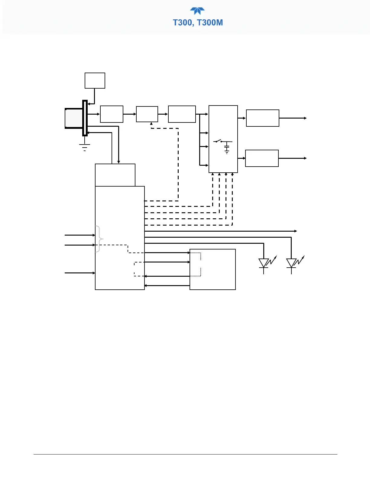
Additionally the synch/demod board contains circuitry that controls the photo-detector’s
thermoelectric cooler as well as circuitry for performing certain diagnostic tests on the
analyzer.
Thermo-Electric
Cooler
Control Circuit
Sample &
Hold
Circuits
(x4)
Compact
Programmable
Logic Device
From CPU
via Mother
Board
Figure 6-13. T300/T300M Sync/Demod Block Diagram
6.4.3.1 SIGNAL SYNCHRONIZATION AND DEMODULATION
The signal emitted by the IR photo-detector goes through several stages of amplification
before it can be accurately demodulated. The first is a pre-amplification stage that raises
the signal to levels readable by the rest of the sync/demod board circuitry. The second is
a variable amplification stage that is adjusted at the factory to compensate for
performance variations of mirrors, detectors, and other components of the optical bench
from instrument to instrument.
The workhorses of the sync/demod board are the four sample-and-hold circuits that
capture various voltage levels found in the amplified detector signal needed to determine
the value of CO MEAS and CO REF. They are activated by logic signals under the
control of a compact Programmable Logic Device (PLD), which in turn responds to the
output of the Segment Sensor and M/R Sensor as shown in Figure 6-9.
The four sample and hold circuits are designated as follows: