083730300A DCN8101 Getting Started 31
Table 2-5. Control Input Signals
INPUT # STATUS DEFINITION ON CONDITION
A
REMOTE ZERO CAL
The analyzer is placed in Zero Calibration mode.
B
REMOTE SPAN CAL
The analyzer is placed in span calibration mode as part of performing a low
span (midpoint) calibration.
C
REMOTE CAL HIGH RANGE
The analyzer is forced into high range for zero or span calibrations. This
only applies when the range mode is either DUAL or AUTO.
D, E
& F
SPARE
Digital Ground
The ground level from the analyzer’s internal DC power supplies (same as
chassis ground).
Input pin for +5 VDC required to activate pins A – F.
+
5 VDC output
Internally generated 5V DC power. To activate inputs A – F, place a jumper
between this pin and the “U” pin. The maximum amperage through this port
is 300 mA (combined with the analog output supply, if used).
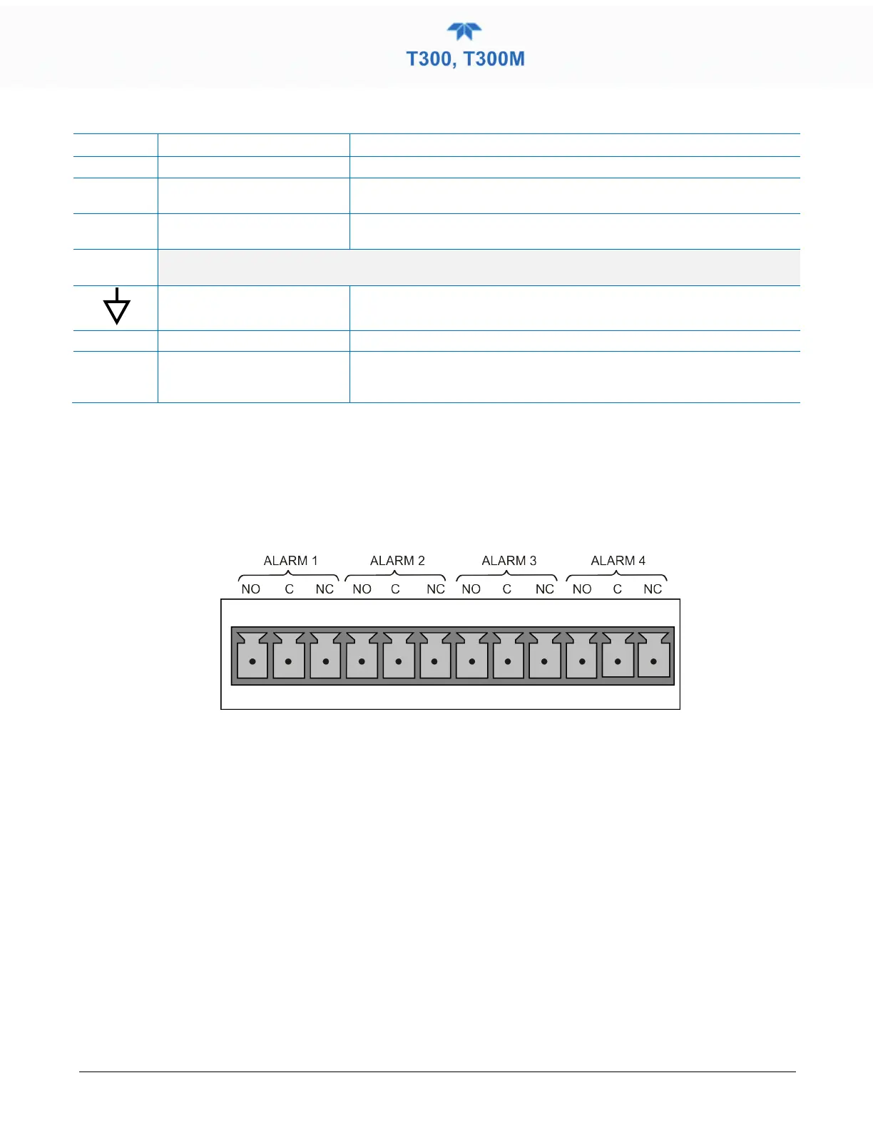
2.3.1.6 CONNECTING THE CONCENTRATION ALARM RELAY (OPTION 61)
The concentration alarm option provides four (4) “dry contact” relays on the rear panel
(Figure 2-10) , each with 3 pins: Common (C), Normally Open (NO), and Normally
Closed (NC). The Relays can be mapped to reflect various internal instrument conditions
and states. ConFigure these outputs through the Setup>Digital Outputs menu
(Section 2.5.7) under MB Relay [1 thru 4].
Figure 2-10. Concentration Alarm Relay
2.3.1.7 CONNECTING THE COMMUNICATION INTERFACES
For remote communications, the rear panel provides Ethernet, USB, RS-232, optional
RS-232 Multidrop, and optional RS-485 connectors. In addition to using the appropriate
cables, each type of communication method must be configured using the
SETUP>COMM menu, Section 2.5.10).
ETHERNET CONNECTION
For network or Internet communication with the analyzer, connect an Ethernet cable from
the analyzer’s rear panel Ethernet interface connector to an Ethernet access port.
Although Ethernet is DHCP-enabled by default, it should be manually configured
(Section 2.5.10.5) with a static IP address.