083730300A DCN8101 Getting Started 79
Recording
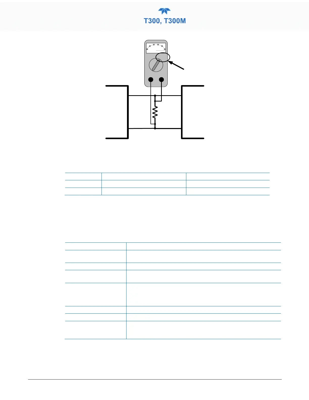
Device
V IN +
V IN -
ANALYZER
V OUT +
V OUT -
250 Ω
Volt
Meter
Figure 2-56. Alternative Setup Using 250Ω Resistor for Checking Current Output Signal Levels
In this case, follow the procedure above but adjust the output for the following values:
Table 2-16. Current Loop Output Check
Voltage across Resistor for 2-20 mA
Voltage across Resistor for 4-20 mA
0 500 mVDC 1000 mVDC
100 5000 mVDC 5000 mVDC
2.5.9 SETUP>INSTRUMENT
As presented in Table 2-17, view product and system information and network settings,
edit network settings, and perform certain maintenance tasks.
Table 2-17. Setup>Instrument Menu
Product Info View Model, Part, and Serial Numbers and Package and Driver Versions,
and options information.
System Info View Windows and RAM information.
Network Settings View the network settings (configurable through the
Setup>Comm>Network Settings menu).
Date/Time Settings Adjust date, hour, and minutes, select a time zone*, and set the system
clock to automatically adjust for Daylight Savings Time or not. (Also see
Setup>Vars>Daylight Savings Enable). *Time Zone change requires a
special procedure; see Maintenance Section 5.5.
NTP Time Settings ConFigure Network Time Protocol settings for clock synchronization.
Language Select an available language.
Remote Update When an instrument is connected to a network that is connected to the
Internet, follow the instructions on this Remote Update page to check for
and activate software/firmware updates. (Also refer to Section
).