134 Maintenance and Service 083730300A DCN8101
In some rare circumstances, this failure may be caused by a bad IC on the motherboard,
specifically U57, the large, 44 pin device on the lower right hand side of the board. If this
is true, removing U57 from its socket will allow the instrument to start up but the
measurements will be invalid.
If the analyzer stops during initialization (the front panel display shows a fault or warning
message), it is likely that the DOM, the firmware or the configuration and data files have
been corrupted.
5.7.17 RS-232 COMMUNICATIONS
5.7.17.1 GENERAL RS-232 TROUBLESHOOTING
Teledyne API analyzers use the RS-232 communications protocol to allow the instrument
to be connected to a variety of computer-based equipment. RS-232 has been used for
many years and as equipment has become more advanced, connections between various
types of hardware have become increasingly difficult. Generally, every manufacturer
observes the signal and timing requirements of the protocol very carefully.
Problems with RS-232 connections usually center around the following general areas:
1. Incorrect cabling and connectors. See Section 2.3 for connector and pin-out
information.
2. The BAUD rate and protocol are incorrectly configured. See Section 2.3.1.7 under
RS-232.
3. Incorrect setting of the DTE-DCE Switch. Ensure that switch is set correctly. See
Section 3.1.
4. Verify that the cable that connects the serial COM ports of the CPU to J12 of the
motherboard is properly seated.
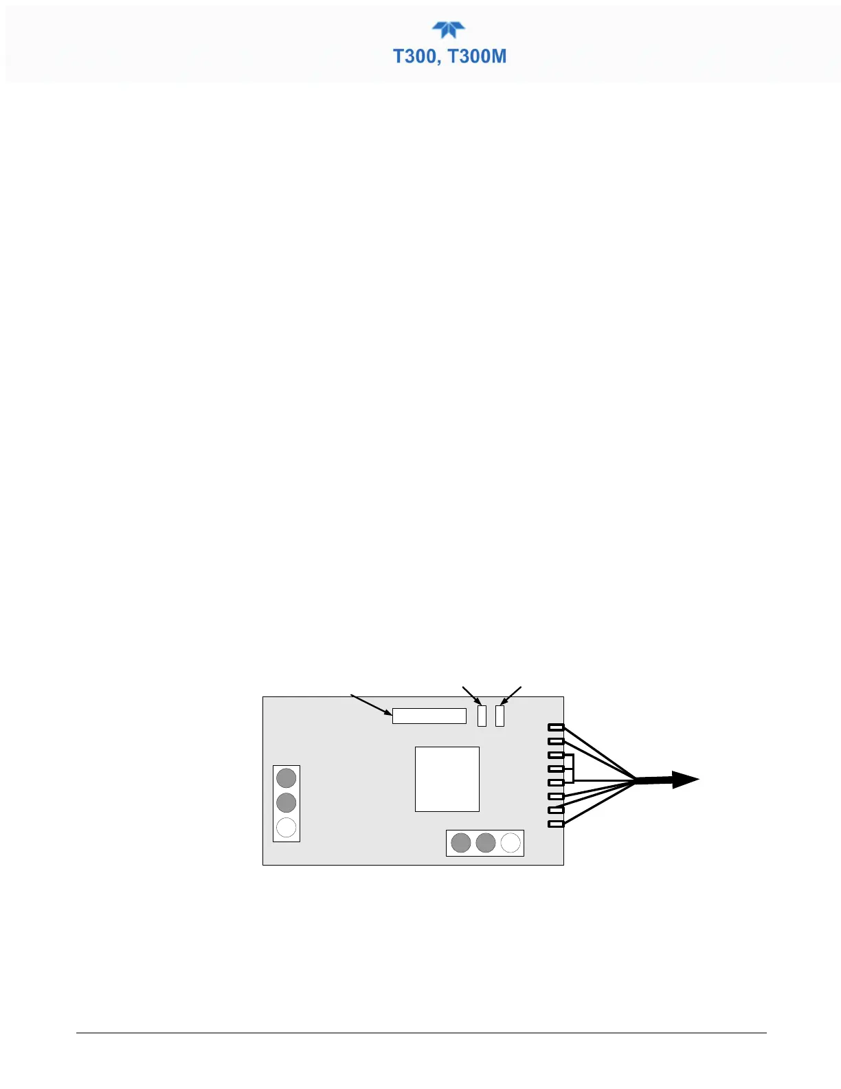
5.7.18 THE OPTIONAL CO
2
SENSOR
There are Two LEDs located on the CO
2
sensor PCA.
CPU
Analog
Output
To CO
2
Probe
OVDC 5VDC
GND +12 V
Power Supply
Connections
LED V8
(Red)
LED V9
(Green)
Serial I
/O
(Not Used)
Figure 5-11. Location of Diagnostic LEDs onCO
2
Sensor PCA
• Normal Operation: V8 is not lit – V9 is Blinking
• Error State: Both LEDs are blinking.
Check to make sure that the cable to the CO
2
probe is properly connected.