083730300A DCN8101 Maintenance and Service 129
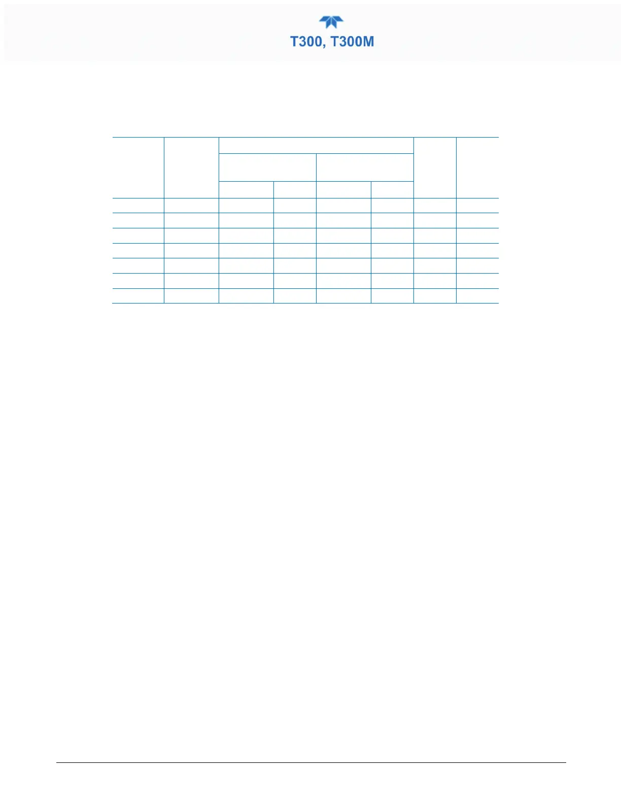
A voltmeter should be used to verify that the DC voltages are correct per the values in the
table below, and an oscilloscope, in AC mode, with band limiting turned on, can be used
to evaluate if the supplies are producing excessive noise (> 100 mV p-p).
Table 5-10. DC Power Supply Acceptable Levels
POWER
SUPPLY
ASSY
VOLTAGE
CHECK RELAY BOARD TEST POINTS
MIN V MAX V
FROM TEST
POINT
TO TEST POINT
PS1 +5 Dgnd 1 +5 2 4.8 5.25
PS1 +15 Agnd 3 +15 4 13.5 16V
PS1 -15 Agnd 3 -15V 5 -14V -16V
PS1 Agnd Agnd 3 Dgnd 1 -0.05 0.05
PS1 Chassis Dgnd 1 Chassis N/A -0.05 0.05
PS2 +12 +12V Ret 6 +12V 7 11.75 12.5
PS2 Dgnd +12V Ret 6 Dgnd 1 -0.05 0.05
5.7.14.3 I
2
C BUS
Operation of the I
2
C bus can be verified by observing the behavior of D1 on the relay
PCA. Assuming that the DC power supplies are operating properly, the I
2
C bus is
operating properly if D1 on the relay PCA is flashing.
5.7.14.4 TOUCHSCREEN INTERFACE
Verify the functioning of the touchscreen by observing the display when pressing a
touchscreen control button. Assuming that there are no wiring problems and that the DC
power supplies are operating properly, if pressing a control button on the display does not
change the display, any of the following may be the problem:
• The touchscreen controller may be malfunctioning.
• The internal USB bus may be malfunctioning.
You can verify this failure by logging on to the instrument using APICOM or a terminal
program to any of the communications ports. If the analyzer responds to remote
commands and the display changes accordingly, the touchscreen interface may be faulty.
5.7.14.5 LCD DISPLAY MODULE
Verify the functioning of the front panel display by observing it when power is applied to
the instrument. Assuming that there are no wiring problems and that the DC power
supplies are operating properly, the display screen should light and show the splash
screen with logo and other indications of its state as the CPU goes through its
initialization process.