30 Getting Started 083730300A DCN8101
Table 2-4. Status Output Pin Assignments
PIN
STATUS
CONDITION
1-8
Configurable
through the
Setup>Digital
Outputs menu
Collector side of individual status output opto-isolators.
D Emitter BUS
The emitters of the transistors on pins 1 to 8 are bussed
together.
Blank NO CONNECTION
+ DC Power + 5 VDC, 300 mA source maximum
Digital Ground
The ground level from the analyzer’s internal DC power
supplies. This connection should be used as the ground
return when +5VDC power is used.
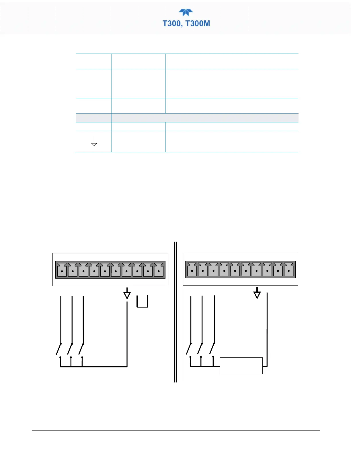
2.3.1.5 CONNECTING THE CONTROL INPUTS (DIGITAL INPUTS)
With zero and span valves option installed, their digital control inputs are provided
through the rear panel 10-pin CONTROL IN connector to remotely activate the zero and
span calibration modes.
Energize the Control Inputs either by the internal +5V available from the pin labeled “+”
(more convenient), or by a separate external 5 VDC power supply (ensures that these
inputs are truly isolated). Refer to Figure 2-9
External Power Connections
Figure 2-9. Control Input Connector