083730300A DCN8101 Theory of Operation 155
6.4.2.3 GFC WHEEL
A synchronous AC motor turns the GFC Wheel motor. For analyzers operating on 60Hz
line power this motor turns at 1800 rpm. For those operating on 50Hz line power the spin
rate is 1500 rpm. The actual spin rate is unimportant within a large range since a phase
lock loop circuit is used to generate timing pulses for signal processing.
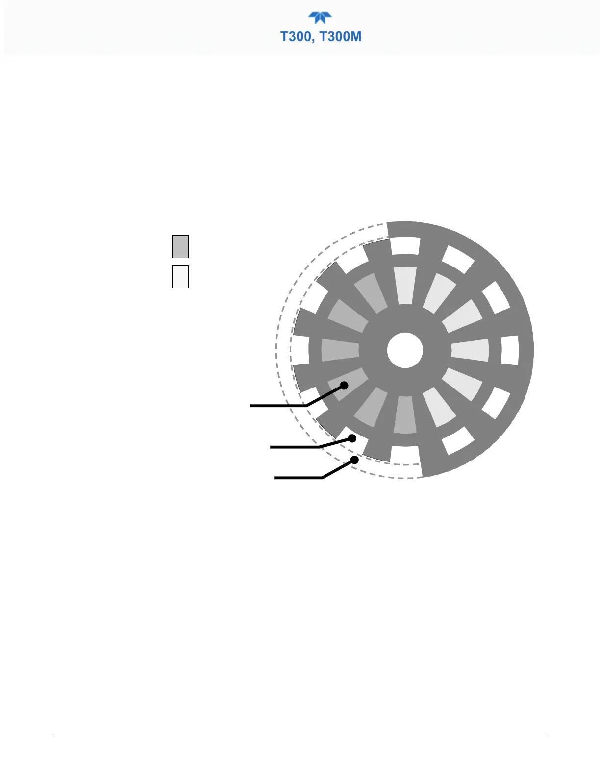
In order to accurately interpret the fluctuations of the IR beam after it has passed through
the sample gas, the GFC Wheel several other timing signals are produced by other photo
emitters/detectors. These devices consist of a combination LED and detector mounted so
that the light emitted by the LED shines through the same mask on the GFC Wheel that
chops the IR beam.
Detection Beam shining
through MEASUREMENT
side of GFC Wheel
Detection Beam shining
through REFERENCE side
of GFC Wheel
Figure 6-11. GFC Light Mask
M/R SENSOR
This emitter/detector assembly produces a signal that shines through a portion of the
mask that allows light to pass for half of a full revolution of the wheel. The resulting
light signal tells the analyzer whether the IR beam is shining through the measurement or
the reference side of the GFC Wheel.