083730300A DCN8101 Getting Started 45
INPUT GAS VENTING
The zero air supply and sample gas line MUST be vented in order to ensure that the gases
input do not exceed the maximum inlet pressure of the analyzer as well as to prevent back
diffusion and pressure effects. These vents should be:
• At least 0.2m long;
• No more than 2m long and;
• Vented outside the shelter or immediate area surrounding the instrument.
A similar vent line should be connected to the VENT SPAN outlet on the back of the
analyzer.
EXHAUST OUTLET
Attach an exhaust line to the analyzer’s EXHAUST outlet fitting. The exhaust line
should be:
• PTFE tubing; minimum O.D ¼”;
• A maximum of 10 meters long;
1. Vented outside the analyzer’s enclosure.
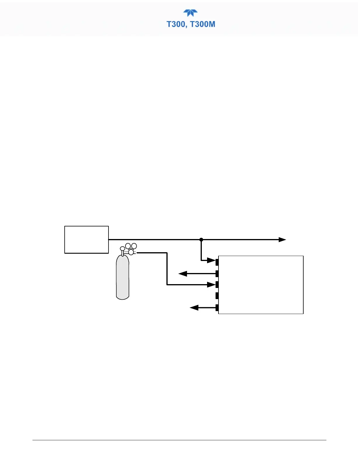
2.3.2.5 PNEUMATIC CONNECTIONS: ZERO SCRUBBER/PRESSURIZED SPAN OPTION
Source of
SAMPLE GAS
Removed during
calibration
VENT
Calibrated
CO Gas
at span gas
concentration
(Adjust to 30
psig)
VENT her e if input
is pressurized
PRESSURE/SPAN
AIR/IZS
SAMPLE
EXHAUST
VENT/SPAN
Instrument
Chassis
Exhaust must be vented
outside of shelter or
immediate area surrounding
the instrument.
Figure 2-19. T300/T300M Pneumatic Connections – Option 50E: Zero Scrubber/Pressurized Span
SAMPLE GAS SOURCE
Attach a sample inlet line to SAMPLE inlet port. The sample input line should not be
more than 2 meters long.
• Maximum pressure of any gas at the sample inlet should not exceed 1.5 in-hg above
ambient pressure and ideally should equal ambient atmospheric pressure.
• In applications where the sample gas is received from a pressurized manifold, a vent must
be placed on the sample gas before it enters the analyzer.