083730300A DCN8101 Maintenance and Service 133
5.7.15.2 STATUS OUTPUTS
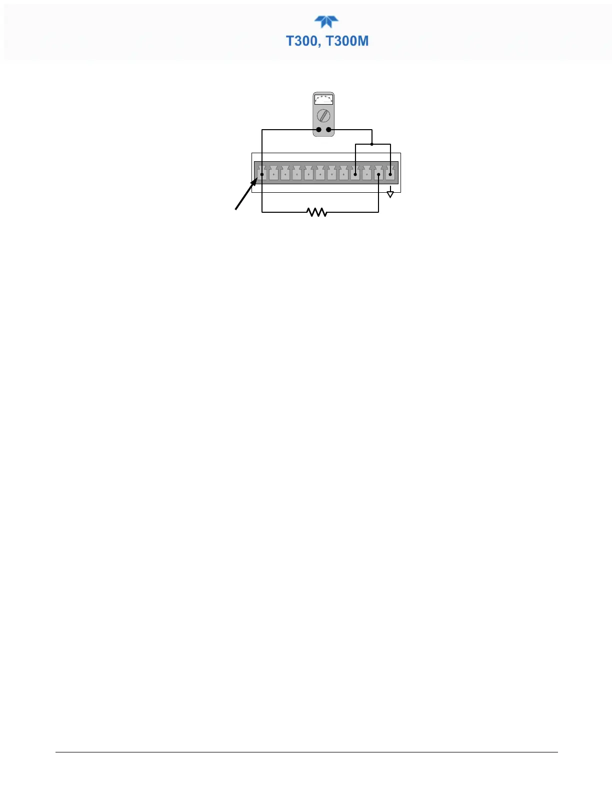
Figure 5-10. Typical Set Up of Status Output Test
The procedure below can be used to test the Status outputs:
1. Connect a jumper between the “D“ pin and the “” pin on the status output
connector.
2. Connect a 1000 ohm resistor between the “+” pin and the pin for the status output
that is being tested.
3. Connect a voltmeter between the “” pin and the pin of the output being tested (see
table below).
4. In the Utilities>Diagnostics>Digital Outputs menu (see Section 5.7.4), scroll through
the outputs until you get to the output in question.
5. Alternatively, turn on and off the output noting the voltage on the voltmeter.
• It should vary between 0 volts for ON and 5 volts for OFF.
5.7.15.3 CONTROL INPUTS – REMOTE ZERO, SPAN
The control input bits can be tested by the following procedure:
1. Jumper the +5 pin on the Status connector to the U on the Control In connector.
2. Connect a second jumper from the
_
pin on the Status connector to the A pin on the
Control In connector. The instrument should switch from Sample Mode to ZERO
CAL R mode.
3. Connect a second jumper from the
_
pin on the Status connector to the B pin on the
Control In connector. The instrument should switch from Sample Mode to SPAN
CAL R mode.
4. In each case, the T300/T300M should return to Sample Mode when the jumper is
removed.
5.7.16 CPU
There are two major types of CPU board failures, a complete failure and a failure
associated with the Disk On Module (DOM). If either of these failures occurs, contact the
factory.
For complete failures, assuming that the power supplies are operating properly and the
wiring is intact, the CPU is faulty if on power-on, the watchdog LED on the motherboard
is not flashing.
 Loading...