48 Getting Started 083730300A DCN8101
EXHAUST OUTLET
Attach an exhaust line to the analyzer’s EXHAUST outlet fitting. The exhaust line
should be:
• PTFE tubing; minimum O.D ¼”;
• A maximum of 10 meters long;
• Vented outside the analyzer’s enclosure.
2.3.3 PNEUMATIC FLOW DIAGRAMS
This Section shows the basic pneumatic flow diagram followed by flow diagrams with
options 50A Ambient Zero/Ambient Span, 50B Ambient Zero/Pressurized Span, 50E
Zero Scrubber/Pressurized Span, and 50H Zero Scrubber/Ambient Span. Tables with the
valve operating states follow each of the flow diagrams with valve options.
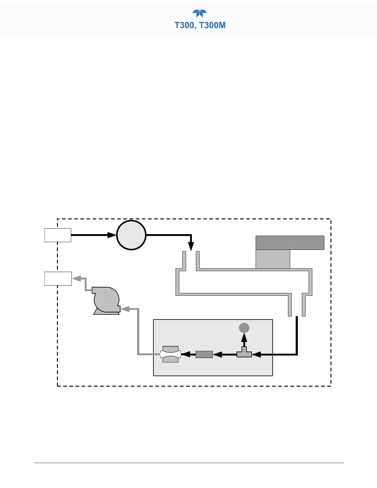
2.3.3.1 PNEUMATIC FLOW: BASIC CONFIGURATION
INSTRUMENT CHASSIS
Flow / Pressure
Sensor PCA
SAMPLE
PRESSURE
SENSOR
FLOW
SENSOR
Sample Gas
Flow Control
SAMPLE GAS
INLET
EXHAUST
GAS OUTLET
Particulate Filter
PUMP
GFC Wheel
Housing
GFC Motor Heat Sync
SAMPLE CHAMBER
Figure 2-21. T300/T300M Internal Gas Flow (Basic Configuration)