ePWM
C2000 Microcontroller Workshop - Control Peripherals 7 - 5
ePWM
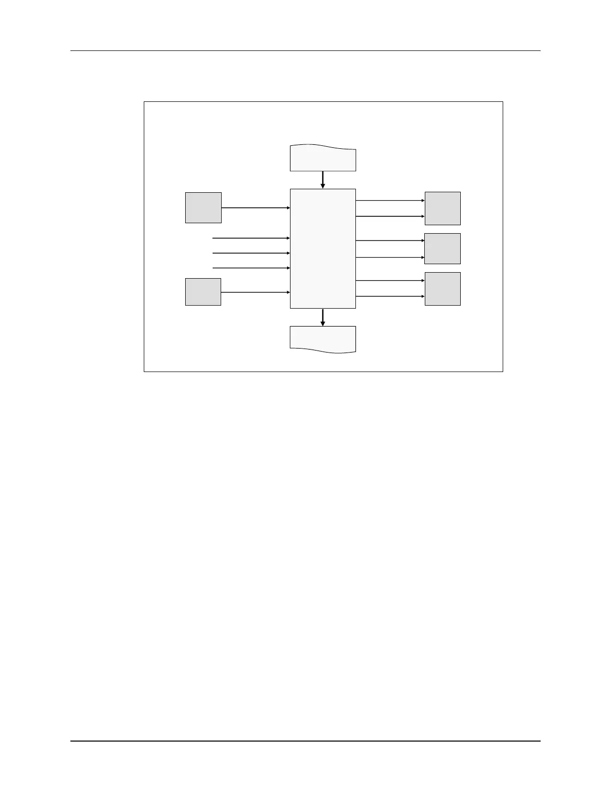
ePWM Module Signals and Connections
ePWMx
ePWMx
+1
EPWMxSYNCI
EPWMxSYNCO
PIE
EPWMxINT
EPWMxTZINT
ePWMx
-1
EPWMxSOCB
EPWMxSOCA
ADC
COMP
COMPxOUT
EMUSTOP – TZ6
CLOCKFAIL – TZ5
EQEP1ERR – TZ4
CPU
SYSCTRL
eQEP1
EPWMxA
EPWMxB
GPIO
MUX
TZ1 – TZ3
GPIO
MUX
An ePWM module can be synchronized with adjacent ePWM modules. The generated PWM
waveforms are available as outputs on the GPIO pins. Additionally, the EPWM module can
generate ADC starter conversion signals and generate interrupts to the PIE block. External trip
zone signals can trip the output and generate interrupts, too. The outputs of the comparators are
used as inputs to the digital compare sub-module. Next, we will look at the internal details of the
ePWM module.