ADC Conversion Result Registers
Sequential Sampling Mode (SIMULENx = 0)
After ADC completes a conversion of an SOCx, the digital result is
placed in the corresponding ADCRESULTx register
Simultaneous Sampling Mode (SIMULENx = 1)
After ADC completes a conversion of a channel pair, the digital
results are found in the corresponding ADCRESULTx and
ADCRESULTx+1 registers
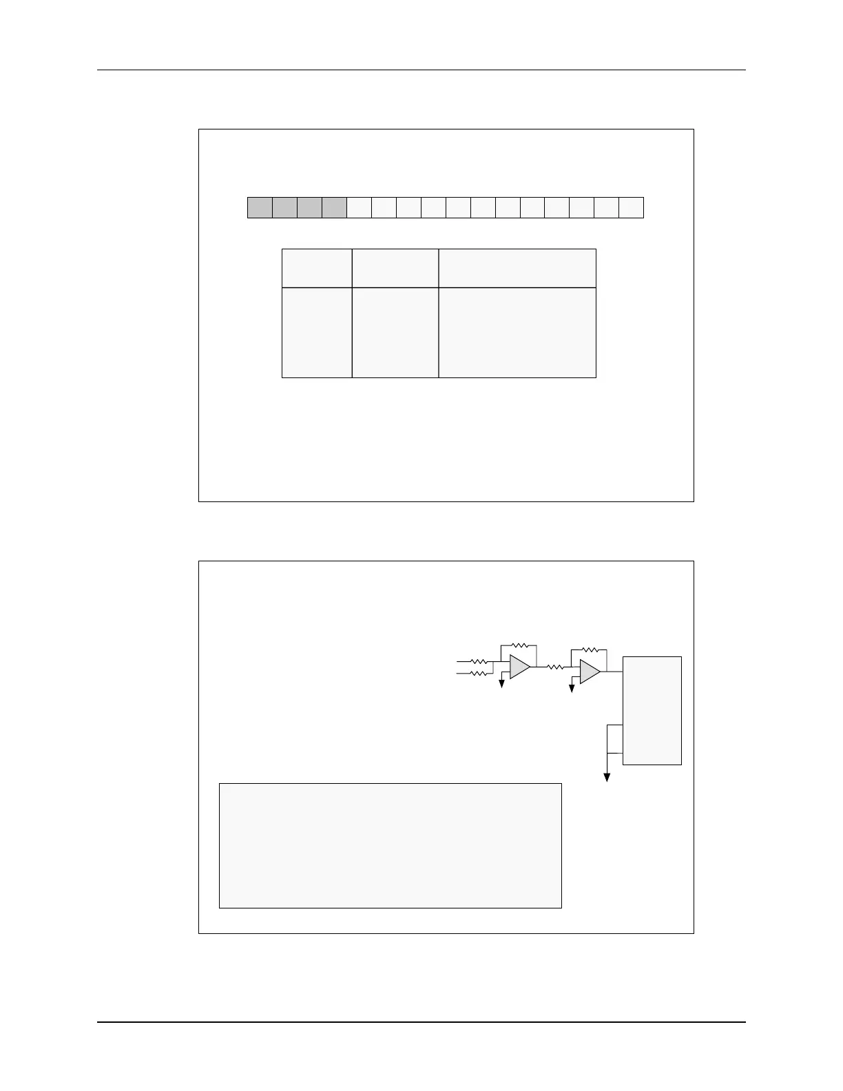
Input Digital AdcResult.
Voltage Result ADCRESULTx
3.3 FFFh 0000|1111|1111|1111
1.65 7FFh 0000|0111|1111|1111
0.00081 1h 0000|0000|0000|0001
0 0h 0000|0000|0000|0000
LSBMSB
15 14 13 12 11 10 9 8 7 6 5 4 3 2 1 0
AdcResult.ADCRESULTx, x = 0 - 15
How Can We Handle Signed Input Voltages?
Example: -1.65 V
≤
V
in
≤
+1.65 V
1) Add 1.65 volts to the
analog input
V
in
1.65V
ADCINx
GND
ADCLO
-
+
R
R
R
-
+
R
R
C28x
#include “F2806x_Device.h”
#define offset 0x07FF
void main(void)
{
int16 value; // signed
value = AdcResult.ADCRESULT0 – offset;
}
2) Subtract “1.65” from the digital result