Interrupts
4 - 14 C2000 Microcontroller Workshop - Reset and Interrupts
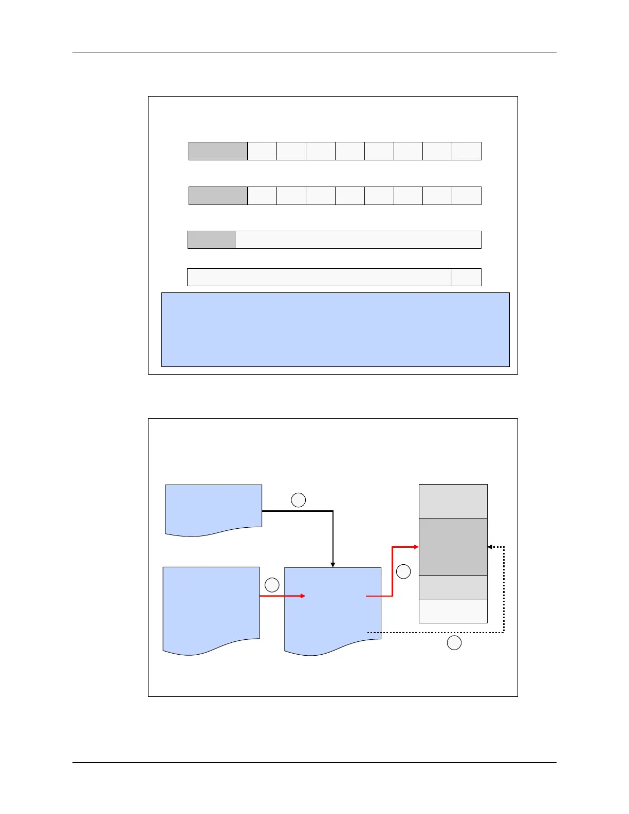
PIE Registers
INTx.2INTx.3INTx.4INTx.5INTx.6INTx.7INTx.8 INTx.1
0123456715 - 8
reserved
PIEIFRx register (x = 1 to 12)
INTx.2INTx.3INTx.4INTx.5INTx.6INTx.7INTx.8 INTx.1
0123456715 - 8
reserved
PIEIERx register (x = 1 to 12)
reserved
PIEACKx
PIE Interrupt Acknowledge Register (PIEACK)
124 356789 0101115 - 12
ENPIE
PIEVECT
PIECTRL register
0
15 - 1
#include “F2806x_Device.h”
PieCtrlRegs.PIEIFR1.bit.INTx4 = 1; //manually set IFR for XINT1 in PIE group 1
PieCtrlRegs.PIEIER3.bit.INTx2 = 1; //enable EPWM2_INT in PIE group 3
PieCtrlRegs.PIEACK.all = 0x0004; //acknowledge the PIE group 3
PieCtrlRegs.PIECTRL.bit.ENPIE = 1; //enable the PIE
PIE Block Initialization
PIE Block Initialization
•
•
•
// CPU Initialization
InitPieCtrl();
•
•
•
Main.c
•
•
•
// Initialize PIE_RAM
memcpy( );
•
•
•
PieCtrl.c
// Enable PIE Block
PieCtrlRegs.
PIECTRL.bit.
ENPIE=1;
•
•
•
•
•
•
// Base Vectors
PieVect.c
PIE_VECT_TABLE
•
•
•
// Core INT1 re-map
// Core INT12 re-map
PIE RAM
Vectors
256w
(ENPIE = 1)
Boot ROM
Reset Vector
1
2
2
3
Memory Map
The interrupt vector table, as mapped in the PIE interrupt assignment table, is located in the
PieVect.c file. During initialization in main, we have a function call to PieCtrl.c. In this file, a