Reset
4 - 4 C2000 Microcontroller Workshop - Reset and Interrupts
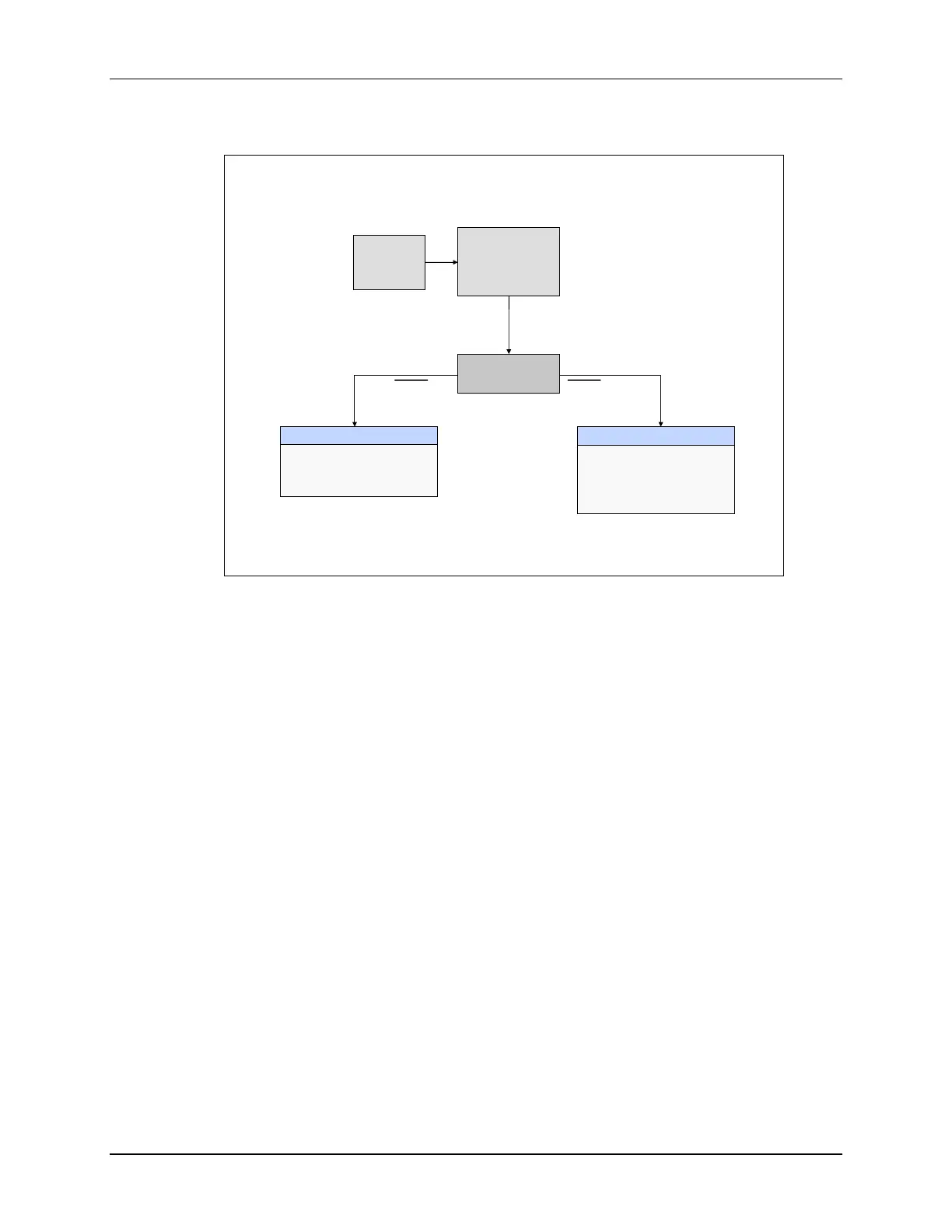
Reset - Bootloader
Reset – Bootloader
TRST = JTAG Test Reset
EMU_KEY & EMU_BMODE located in PIE at 0x0D00 & 0x0D01, respectively
OTP_KEY & OTP_BMODE located in OTP at 0x3D7BFB & 0x3D7BFE, respectively
Reset vector
fetched from
boot ROM
0x3F FFC0
Emulation Boot
Boot determined by
2 RAM locations:
EMU_KEY and EMU_BMODE
Stand-alone Boot
Boot determined by
2 GPIO pins and
2 OTP locations:
OTP_KEY and OTP_BMODE
TRST = 1 TRST = 0
Reset
ENPIE = 0
INTM = 1
YES
NO
Emulator
Connected ?
After reset, the PIE block is disabled and the global interrupt line is disabled. The reset vector is
fetched from the boot ROM and the bootloader process begins.
Then the bootloader determines if the emulator is connected by checking the JTAG test reset line.
If the emulator is connected, we are in emulation boot mode. The boot is then determined by two
RAM locations named EMU_Key and EMU_BMODE, which are located in the PIE block. If the
emulator is not connected, we are in stand-alone boot mode. The boot is then determined by two
GPIO pins and two OTP locations named OTP_KEY and OTP_BMODE, which are located in
the OTP.