Reset
4 - 6 C2000 Microcontroller Workshop - Reset and Interrupts
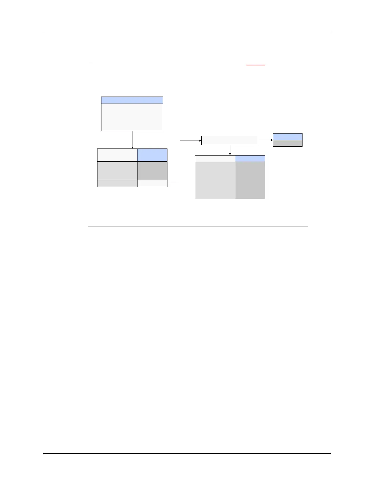
Stand-Alone Boot Mode
Stand-Alone Boot Mode
(TRST = 0)
Stand-alone Boot
Boot determined by
2 GPIO pins and
2 OTP locations:
OTP_KEY and OTP_BMODE
Emulator Not Connected
Boot Mode
Parallel I/O
SCI
Wait
GetMode
GPIO GPIO
37 34
0 0
0 1
1 0
1 1
Boot Mode
FLASH
Boot Mode
SCI
SPI
I2C
OTP
CAN
FLASH
OTP_BMODE =
0x0001
0x0004
0x0005
0x0006
0x0007
other
NO
YES
Note that the boot behavior for
unprogrammed OTP is the
“FLASH” boot mode
OTP_KEY = 0x005A ?
In stand-alone boot mode, GPIO pins 37 and 34 determine if the boot mode is parallel I/O, SCI,
or wait. The default unconnected pins would set the boot mode to GetMode. In GetMode, first
the OTP_KEY register is checked to see if it has a value of 0x005A. An unprogrammed OTP is
set to the FLASH boot mode, as expected.
If the OTP_KEY register has a value of 0x005A, then the hex value in the OTP_BMODE register
determines the boot mode. The boot modes are SCI, SPI, I2C, OTP, CAN, and FLASH.
Reset Code Flow – Summary
In summary, the reset code flow is as follows: The reset vector is fetched from the boot ROM.
Then, the execution entry is determined by emulation boot mode or stand-alone boot mode. The
boot mode options are M0SARAM, OTP, FLASH, and boot loading routines.

 Loading...


