Interrupts
C2000 Microcontroller Workshop - Reset and Interrupts 4 - 13
peripheral interrupt expansion block. This block is connected to the core interrupt lines 1 through
12. The PIE block consists of 12 groups. Within each group, there are eight interrupt sources.
Each group has a PIE interrupt enable register and a PIE interrupt flag register.
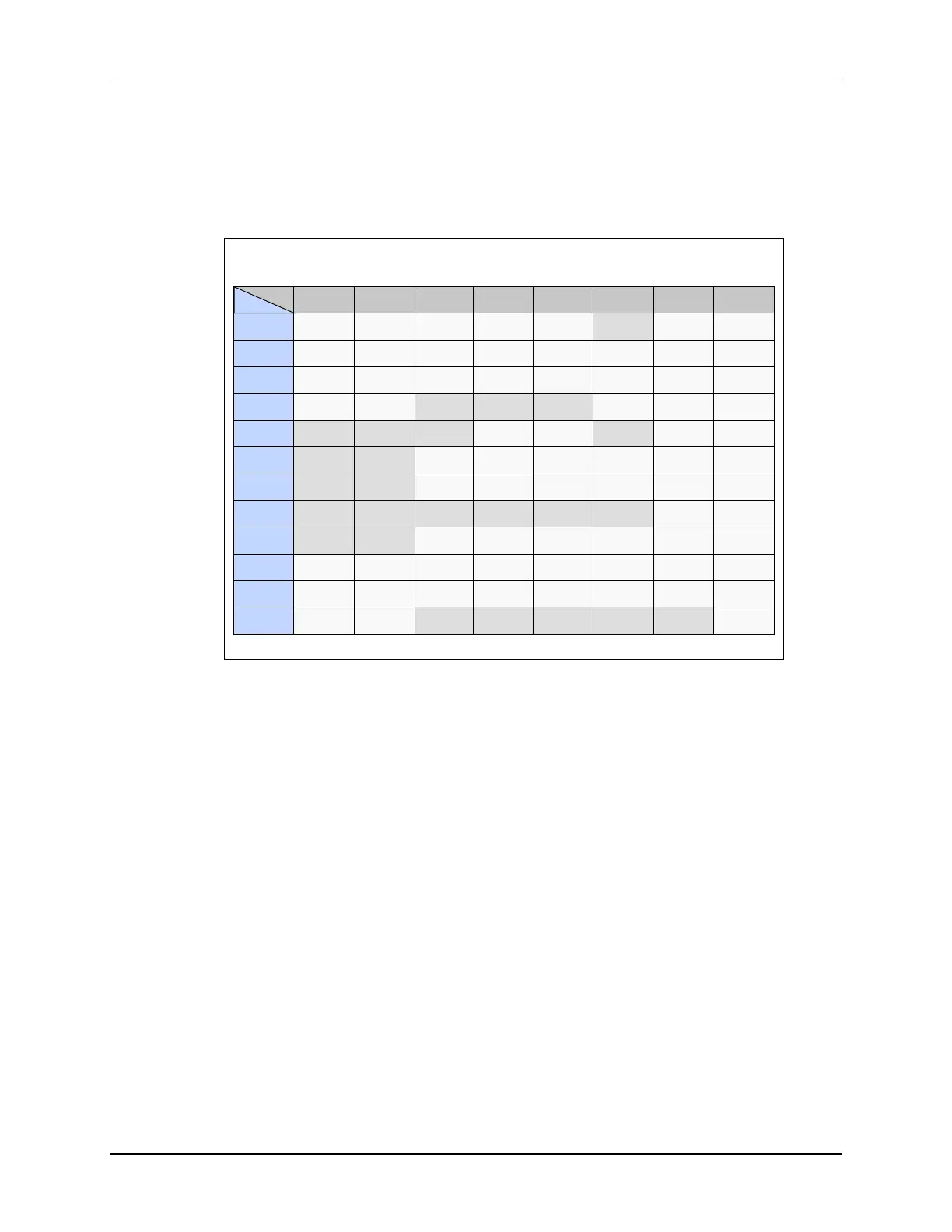
As you can see, the interrupts are numbered from 1.1 through 12.8, giving us a maximum of 96
interrupt sources. Interrupt lines 13, 14, and NMI bypass the PIE block.
F2806x PIE Interrupt Assignment Table
INTx.8
INTx.7 INTx.6
INTx.5 INTx.4 INTx.3 INTx.2 INTx.1
INT1
WAKEINT
TINT0 ADCINT9 XINT2 XINT1 ADCINT2 ADCINT1
INT2
EPWM8
_TZINT
EPWM7
_TZINT
EPWM6
_TZINT
EPWM5
_TZINT
EPWM4
_TZINT
EPWM3
_TZINT
EPWM2
_TZINT
EPWM1
_TZINT
INT3
EPWM8
_INT
EPWM7
_INT
EPWM6
_INT
EPWM5
_INT
EPWM4
_INT
EPWM3
_INT
EPWM2
_INT
EPWM1
_INT
INT4
HRCAP2
_INT
HRCAP1
_INT
ECAP3
_INT
ECAP2
_INT
ECAP1
_INT
INT5
HRCAP4
_INT
HRCAP3
_INT
EQEP2
_INT
EQEP1
_INT
INT6
MXINTA MRINTA
SPITX
INTB
SPIRX
INTB
SPITX
INTA
SPIRX
INTA
INT7
DINTCH6 DINTCH5 DINTCH4 DINTCH3 DINTCH2 DINTCH1
INT8
I2CINT2A
I2CINT1A
INT9
SCITX
INTB
SCIRX
INTB
SCITX
INTA
SCIRX
INTA
INT10
ADCINT8
ADCINT7 ADCINT6
ADCINT5 ADCINT4 ADCINT3
ADCINT2 ADCINT1
INT11
CLA1
_INT8
CLA1
_INT7
CLA1
_INT6
CLA1
_INT5
CLA1
_INT4
CLA1
_INT3
CLA1
_INT2
CLA1
_INT1
INT12
LUF LVF XINT3
ECAN0
_INTA
ECAN1
_INTA
The interrupt assignment table tells us the location for each interrupt source within the PIE block.
Notice the table is numbered from 1.1 through 12.8, perfectly matching the PIE block.
The PIE registers consist of 12 PIE interrupt flag registers, 12 PIE interrupt enable registers, a
PIE interrupt acknowledge register, and a PIE control register. The enable PIE bit in the PIE
control register must be set during initialization for the PIE block to be enabled.

 Loading...


