Receiver Setup
P/N 7010-0557 www.topconpositioning.com
3-3
1. Measure the antenna height above the point or marker.
Figure 3-1 illustrates the antenna offsets. (See Figure 1-5
on page 1-17 and Figure 1-7 on page 1-19 for the exact
SHMM location.)
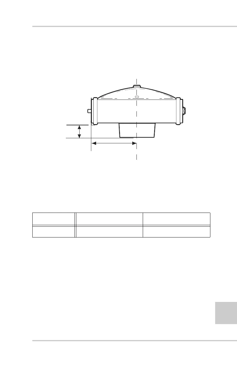
Figure 3-1. HiPer Lite and HiPer Lite+ Antenna Offsets
• SHMM to ARP vertical offset = 30.50mm
• SHMM to ARP horizontal offset = 77.75mm
Table 3-1gives the offset values for the receivers.
The point to which surveying with GPS/GLONASS
measures is called the Phase Center of the antenna. This is
analogous to the point at which a distance meter measures
in a prism. A user must enter the prism offset to
compensate for this point not being at a physical surface of
the prism. In the case of a GPS/GLONASS antenna, the
offset is entered depending on the type of measurement
taken. For vertical, the offset is simply added to the
measured vertical height to produce a “true” vertical height.
For slant height, the vertical height must first be calculated
Table 3-1. Antenna Offset Values for Receiver Options
To L1 Phase Center To L2 Phase Center
Up 106.1mm 95.7mm
SHMM
ARP
30.50mm
77.75mm