Multi Pro 1750Page 7 − 14Drive Train
Transaxle Driveshaft
1
2
3
3
4
4
5
7
6
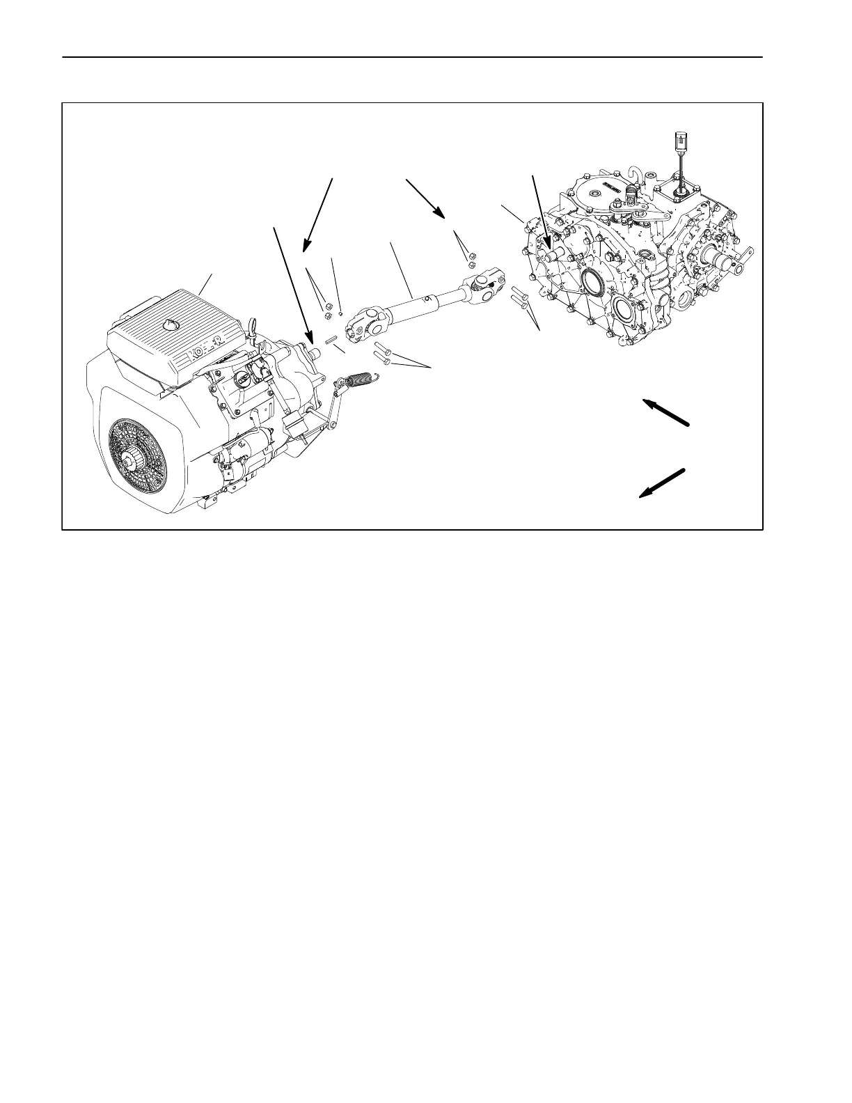
1. Transaxle assembly
2. Engine
3. Cap screw (4 )
4. Lock nut (4)
5. Transaxle driveshaft
6. Set screw
7. Square key
Figure 8
FRONT
RIGHT
90 to 120 in−lb
(10.2 to 13.5 N−m)
Antiseize
Lubricant
Antiseize
Lubricant
Driveshaft Removal (Fig. 8)
1. Park machine on a level surface, stop spray pump,
stop engine and engage parking brake. Remove key
from ignition switch.
2. To remove driveshaft from transaxle, loosen and re-
move lock nuts and cap screws securing driveshaft to
splined input shaft of transaxle. Slide driveshaft yoke
from transaxle.
3. To remove driveshaft yoke from clutch bell housing,
loosen and remove lock nuts and cap screws securing
driveshaft to output shaft at bell housing. Remove set
screw (item 6) from yoke and then slide driveshaft yoke
from shaft. Locate and retrieve square key.
Driveshaft Installation (Fig. 8)
1. Apply antiseize lubricant to clutch bell housing out-
put shaft and transaxle input shaft
2. Position transaxle driveshaft to clutch bell housing
and transaxle shafts. Make sure that square key is
placed in shaft key slot.
3. Slide driveshaft yokes onto clutch bell housing and
transaxle shafts.
4. Install cap screws and lock nuts to secure driveshaft
yoke to output shaft at bell housing. Torque lock nuts
from 90 to 120 in−lb (10.2 to 13.5 N−m). Install and
tighten socket head screw (item 6) into yoke.
5. Install cap screws and lock nuts to secure driveshaft
yoke to splined transaxle input shaft. Torque lock nuts
from 90 to 120 in−lb (10.2 to 13.5 N−m).