E6582062
2. Installation and wiring 2-66
2
9
Circuit diagram 1 is an example in which the standby function is assigned to the terminal [S2]. This
circuit can be applied to a machine that mainly operates horizontally. Set the terminal [S2] to "Open"
to turn off output of the inverter and have the motor in coasting state. Then. operate the brake. If the
brake is operated with inverter output, the inverter may trip due to bound current. Note that when it is
applied to a machine with vertical movements, the motor may fall when it is in coasting state.
Circuit diagram 2 is an example in which low-speed signals are assigned to the terminals [R1A]-
[R1C]. This circuit can be applied also to a machine with vertical movements. At the time of start,
output is made from the inverter while the brake is operating. When the output frequency reaches
<F100: Low-speed signal output frequency>, the brake is released by the signal output from the
terminals [R1A]-[R1C]. When the machine stops, the inverter comes to deceleration stop. When the
output frequency decreases under <F100>, the output signal from the terminals [R1A]-[R1C]
becomes off and the brake operates.
■ Measures to protect motors against surge voltages
In a system in which a 480 V class inverter is used to control the operation of a motor, very high
surge voltages may be produced depending on the wire length, wire routing and types of wires used.
If such surge voltages are applied repeatedly for a long time, it may cause deterioration of insulation
of motor coils.
Here are some examples of measures against surge voltages.
• Decrease <F300: Carrier frequency> of the inverter.
• Use a motor with high insulation strength.
• Insert an AC reactor or a motor-end surge voltage suppression filter between the inverter and the
motor. Refer to [10. 3. 5].
2. 4. 2 Inverters
For the inverters to be used, pay attention to the following items.
■ Inverter capacity
Do not operate a motor whose capacity is larger than the inverter (e.g. a 45 kW motor with a 30 kW
inverter), no matter how light the load is. Current ripple will raise the output peak current, making it
easier to set off the overcurrent trip.
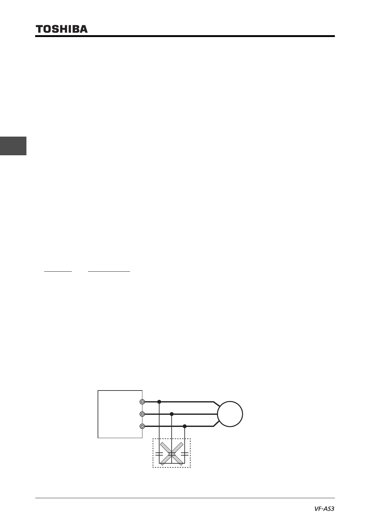
■ Power factor correction capacitor
Power factor correction capacitors cannot be installed on the output side of the inverter. To operate
a motor with a power factor correction capacitor attached, remove the capacitor. Otherwise, it will
cause an inverter malfunction and capacitor destruction.
Inverter
V/T2
U/T1
W/T3
M
Remove power factor correction
capacitors and surge absorber.
Power factor correction capacitor

 Loading...


