10-1 10. Selection and installation of peripheral devices
I
II
III
1
2
3
4
5
6
7
8
9
10
11
12
13
14
15
16
17
18
In this chapter, the selection and installation methods of peripheral devices for this inverter are
described.
According to the voltage class and capacity of the inverter, perform wiring using appropriate wires as
shown in the table below. When connecting peripheral devices to the inverter also, perform wiring accord-
ing to the wire size for a wire location shown in the table below.
• The wire size is a value when using a 600 V HIV insulation wire (copper wire with the maximum allow-
able temperature 75 °C of an insulator) with 50 °C ambient temperature and 30 m or less the length of
each wire.
• For the wire of the control circuit, use a shielded wire with 0.75 mm
2
or more.
10
Selection and installation of
peripheral devices
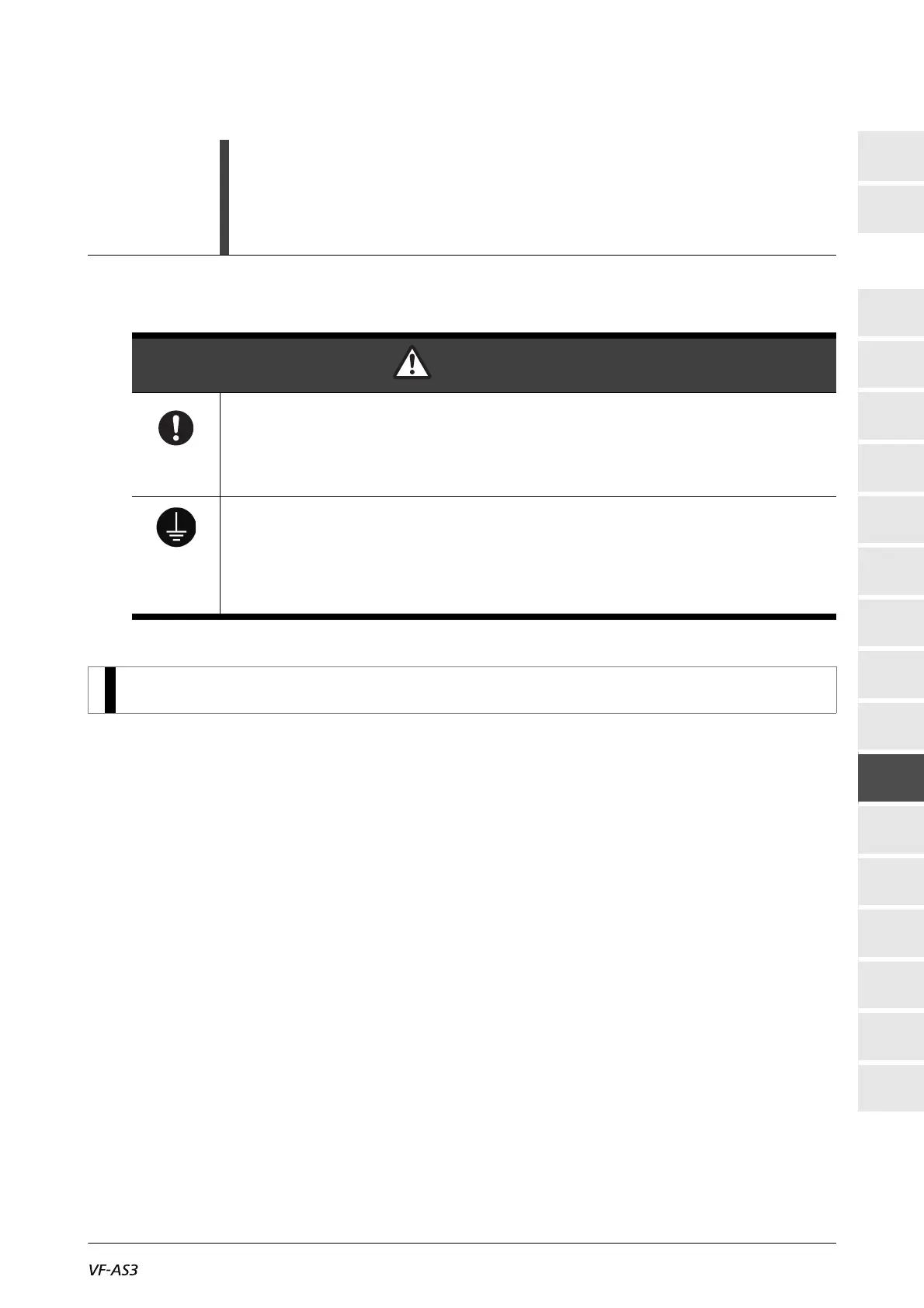
WARNING
Mandatory
action
• All options to be used must be those specified by Toshiba.
The use of options other than those specified by Toshiba will result in an accident.
• In using a power distribution device and options for the inverter, they must be installed in a
cabinet.
When they are not installed in the cabinet, this will result in electric shock.
Be sure to
connect the
grounding
wire.
• The grounding wire must be connected securely.
If the grounding wire is not securely connected, when the inverter has failure or earth leakage,
this will result in electric shock or fire.
10. 1 Selection of wire size

 Loading...


