E6582062
7-19 7. Operating using external signals
3
4
7
9
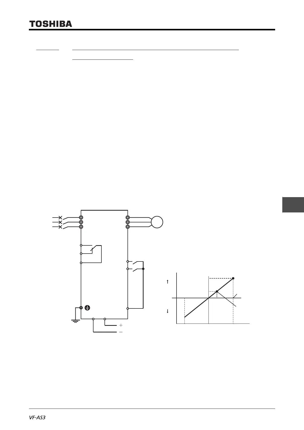
7. 3. 4 Inputting frequency commands by voltage
(-10 to +10 Vdc)
Input the voltage signal of -10 to +10 Vdc between the terminals [RX]-[CC].
You can also input a voltage of 0 - 10 Vdc. Set <F107: Terminal RX input voltage select> = "0: 0 to +10
V".
■ Setting example
The following shows an example of how to externally input the run commands to the digital input
terminals with a voltage input of -10 to +10 V.
The frequency shall be 0 Hz at 0 V, and 60 Hz at +10 V. At this time, the frequency becomes 60 Hz
in reverse run at -10 V.
• <CMOd: Run command select> = "0: Terminal"
• <FMOd: Frequency command select 1> = "2: Terminal RX"
• Set <F107: Terminal RX input voltage select> = "1: -10 to +10 V".
• <F210: RX point 1 input value> = "0" (%) (default setting)
• <F211: RX point 1 frequency> = "0" (Hz) (default setting)
• <F212: RX point 2 input value> = "100" (%) (default setting)
• <F213: RX point 2 frequency> = "60" (Hz) (default setting)
For the characteristics of input currents and output frequencies, set at two points of <F210> and
<F211>, and <F212> and <F213>. The reference for 100% of the input value is 10 V.
(In case of sink logic)
R/L1
S/L2
T/L3
FLA
FLB
FLC
U/T1
V/T2
W/T3
F
Fwd run
-10 to +10 Vdc
Rev run
Fwd
Rev
R
CC
RXCC
Inverter
Motor
M
Output frequency (Hz)
Point 2
Point 1
Voltage signal (%)
-100%
(-10V)
100%
(+10V)
0%
(0V)
Power
supply
<F213>
<F211>
<F210>
<F212>
MCCB
or
ELCB

 Loading...


