E6582062
13-9 13. Trip information and measures
I
II
III
1
2
3
4
5
6
7
8
9
10
11
12
13
14
15
16
17
18
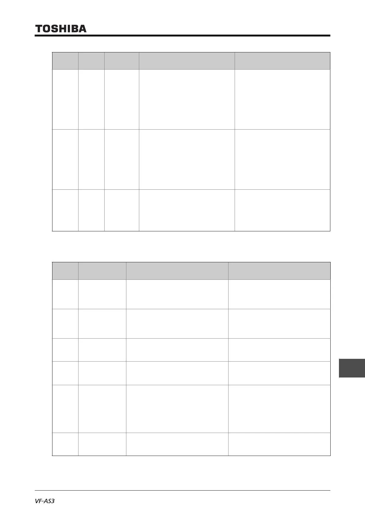
■ Alarm information
UP1 001E Undervoltage
(Power
circuit) *
The input voltage (power circuit) declined. • Check the input voltage.
• Check that the undervoltage detection set-
ting is correct.
<F625: Undervoltage detection level>,
<F627: Undervoltage trip>, etc.
• To avoid trip in momentary power failure,
set <F627> = "0: Disabled", and set
<F301: Auto-restart> and <F302: Regen-
erative power ride-through level> to "1".
Ut 003C Undertorque * The load torque reached the undertorque
level during run.
• Check the load side.
• Check that the undertorque detection set-
ting is correct.
<F651: Undertorque trip>,
<F652: Undertorque detection level during
power running>,
<F653: Undertorque detection level during
regen>,
<F654: Undertorque detection time>, etc.
UtC3 0049 Undertorque/
Undercurrent
*
Undertorque or undercurrent on the shock
monitoring function was detected.
• Check the load.
• When no problem is found, check if the
shock monitoring function setting is
correct.
<F590: Shock monitoring> to <F598:
Shock monitoring detection condition>
*Enable/Disable can be selected for trip with a parameter.
Alarm
display
English Detection factor Measures
A-09 Panel disconnection
alarm
The cable connecting the inverter and panel
are disconnected during run with a run
command from the operation panel and
extension panel.
Check the connection on the inverter and
panel.
A-17 Key failure alarm • [RUN] or [STOP/RESET] key on the operation
panel is pressed and hold for 20 seconds or
more.
• The operation panel key has failed.
Check the operation panel. If the failure
occurs again, contact your Toshiba
distributor.
A-18 Analog input
disconnection alarm
The input level of the terminal [II] became the
setting value or less of <F633: II analog input
disconnection detection level> .
• Check that the signal line connected to the
terminal [II] is not disconnected.
• Check that the <F633> setting is correct.
A-43 Communication
alarm
(embedded Ethernet)
Condition very close to the communication
time out trip.
Perform the same measures with
communication time out "E-43".
COFF Control power
option alarm
1) Undervoltage on the control power supply
input between [+SU] and [CC].
2) The setting of <F647: Control power option
failure detection> is improper.
1) Check the voltage on the control power
supply input between [+SU] and [CC]. 20
Vdc or more is required.
2) When the control power supply option is
not used, set <F647> = "0".
*When [COFF] occurs, turn the power OFF
once, and reset.
MOFF Undervoltage alarm The input voltage (power circuit) declined. Check the input voltage. If no problem is
found, internal error may be the issue.
Contact your Toshiba distributor.
Trip
display
Failure
code
Trip name Detection factor Measures

 Loading...


