E6582062
2-37 2. Installation and wiring
2
3
9
10
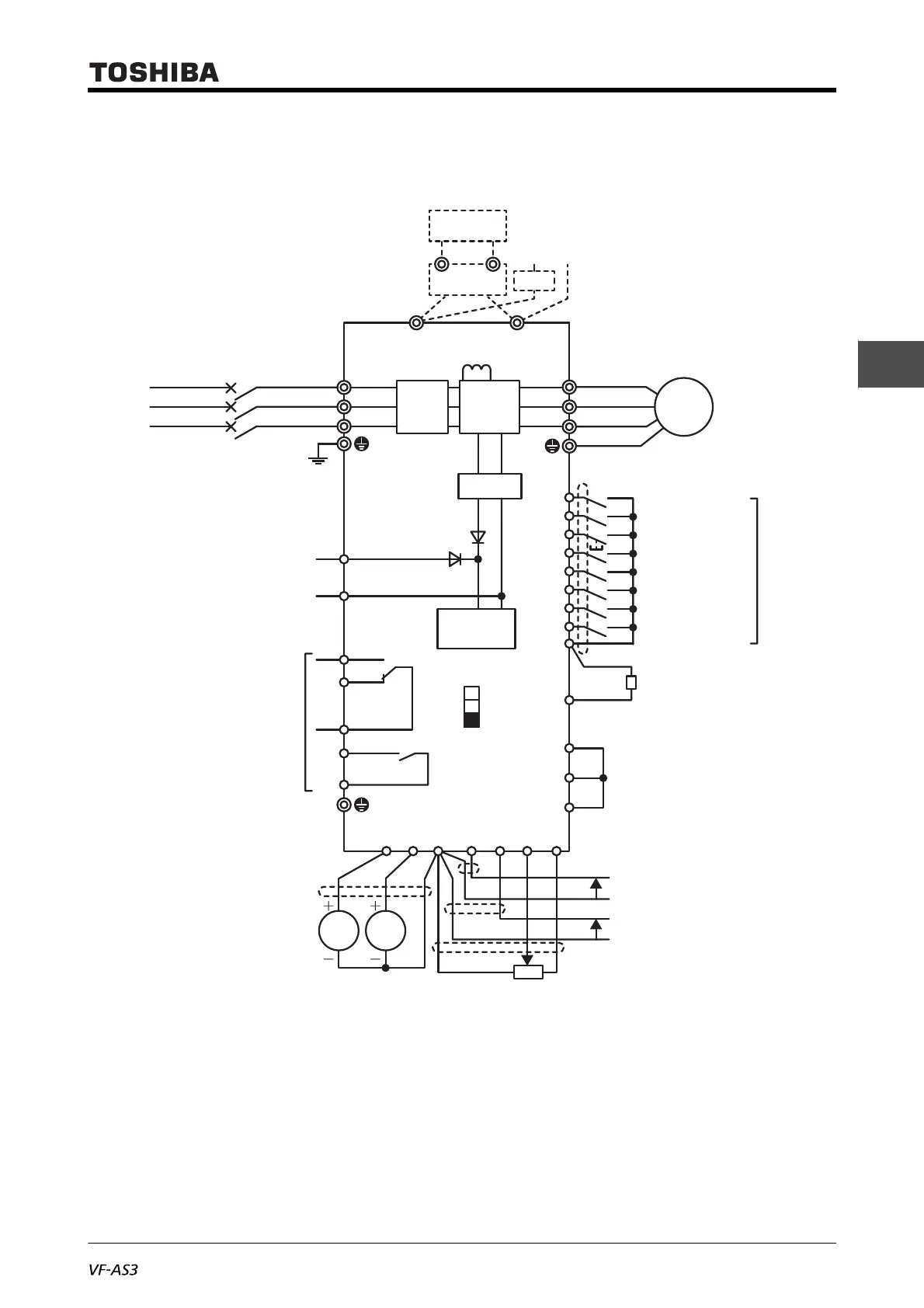
[Standard connection diagram - Source]
This diagram shows an example of a standard connection for 240 V class, 45 to 55 kW and 480 V
class, 90 to 132 kW (frame size A6).
*1 EMC filter is built in 480 V class.
*2 When a braking resistor (optional) is mounted, a braking unit (optional) is also required.
*3 To input DC power, connect the inverter between the terminals [PA/+] and [PC/-].
*4 When the inverter is used with a DC power supply, a circuit to suppress an inrush current is required. For detail, refer to application manual "DC
power supply connect to inverter" (E6582156).
*5 For the switch function, refer to [2. 3. 5].
*6 To supply control power from an external power supply for backing up the control power supplied from the inverter, an optional control power supply
unit (CPS002Z) is required. In this case, it is used in conjunction with the inverter internal power supply.
Set <F647: Control power option failure detection> to back up the control power supply.
For details, refer to [6. 30. 20].
*7 The reset signal is activated by ON→OFF trigger input.
*8 Connect to power to comply with OVC2 (Over Voltage Category 2). Isolation transformer is necessary when connecting to power supply (OVC3).
P24
S5
S4
S3
S2
S1
RES
R
F
+SU
CC
FLA
FLB
FLC
R1A/R2A
R1C/R2C
FM
AM CC RX II RR PP
STOB
STOA
PLC
*6
*1
*3
*2
*2
*4
*6
*8
Power supply
240 V class:
45 - 55 kW Three-phase 200 - 240 V-50/60 Hz
480 V class:
90 - 132 kW Three-phase 380 - 480 V-50/60 Hz
Control
circuit
PLC
SINK
SOURCE
SW1
*5
Pulse counter
FP
Fwd run
Rev run
Reset 1
Preset speed switching 1
Preset speed switching 2
Preset speed switching 3
Preset speed switching 4
Preset speed switching 5
*7
Digital input
Default
setting
DC/DC
Power
circuit
Noise
filter
DC reactor
R/L1
U/T1
V/T2
M
W/T3
PA/+
+DC -DC
PC/-
S/L2
T/L3
MCCB
or
ELCB
Motor
Voltage signal: -10 to +10 V
Ammeter or voltmeter
Current signal :4(0) to 20 mA
(Or, input voltage signal of 0 - 10 V between the terminals [RR] and [CC])
External potentiometer
Frequency
meter
Ammeter

 Loading...


