E6581158
F-39
6
[Parameter setting]
Title Function Adjustment range Default setting
H
Dynamic braking selection
0: Dynamic braking disabled
1: Dynamic braking enabled, over-load
protection enabled
0
H
Dynamic braking resistance
1-1000 (Ω)
H
Dynamic braking resistor
capacity
0.01-30.00 (kW)
According to
model
(See Section
11, K-14)
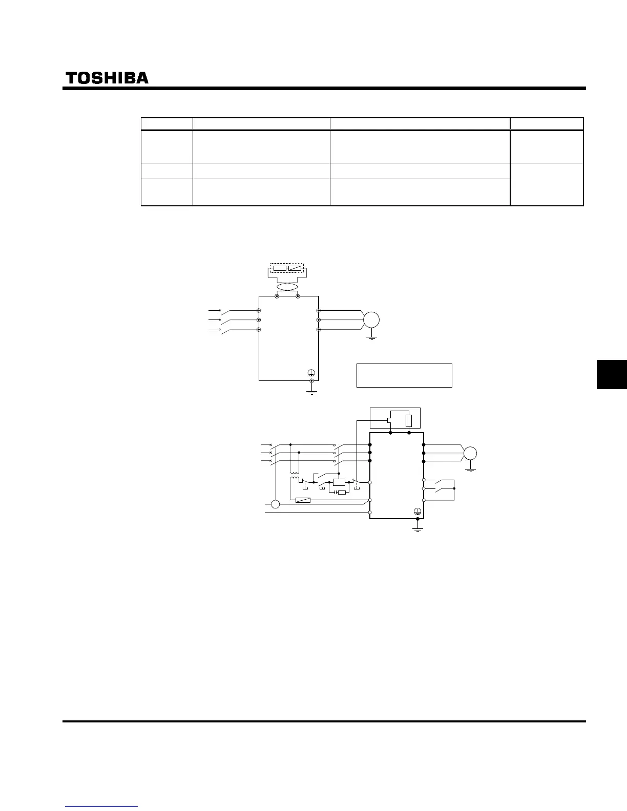
1) Connecting an external braking resistor (optional)
Separate-optional resistor (with thermal fuse)
Surge suppressor
IM
Motor
R/L1
PBR
External braking resistor (optional)
PBR
External braking resistor (optional)
S/L2
T/L3
U/T1
V/T2
W/T3
Inverter
PA
MCCB
Three-phase main circuits
Power supply
PB
MC
MC
MCCB
Three-phase main circuits
Power supply
TC
Fuse
Step-down
transformer
FLB
F
W/T3
V/T2
U/T1
R
CC
Reverse run/stop
Forward run/stop
Inverter
R/L1
PA P B
TH-R
R/L2
R/L3
FLC
FLA
IM
Motor
Connecting thermal relays and
an external braking resistor
2 : 1
Power supply
Note 1: A TC is connected, as shown in this figure, when an MCCB with a trip coil is used instead of an MC.
A step-down transformer is needed for every 400V-class inverter, but not for any 200V-class inverter.
Note 2: As a last resort to prevent fire, be sure to connect a thermal relay (THR). Although the inverter has a
means of preventing overload and overcurrent to protect the braking resistor, the thermal relay is ac-
tivated in case the protection function fails to work. Select and connect a thermal relay (THR) appro-
priate to the capacity (wattage) of the braking resistor.

 Loading...


