E6581158
F-1
6
6. Extended parameters
Extended parameters are provided for sophisticated operation, fine adjustment and other special purposes. Modify
parameter settings as required. See Section 11, Table of extended parameters.
6.1 Input/output parameters
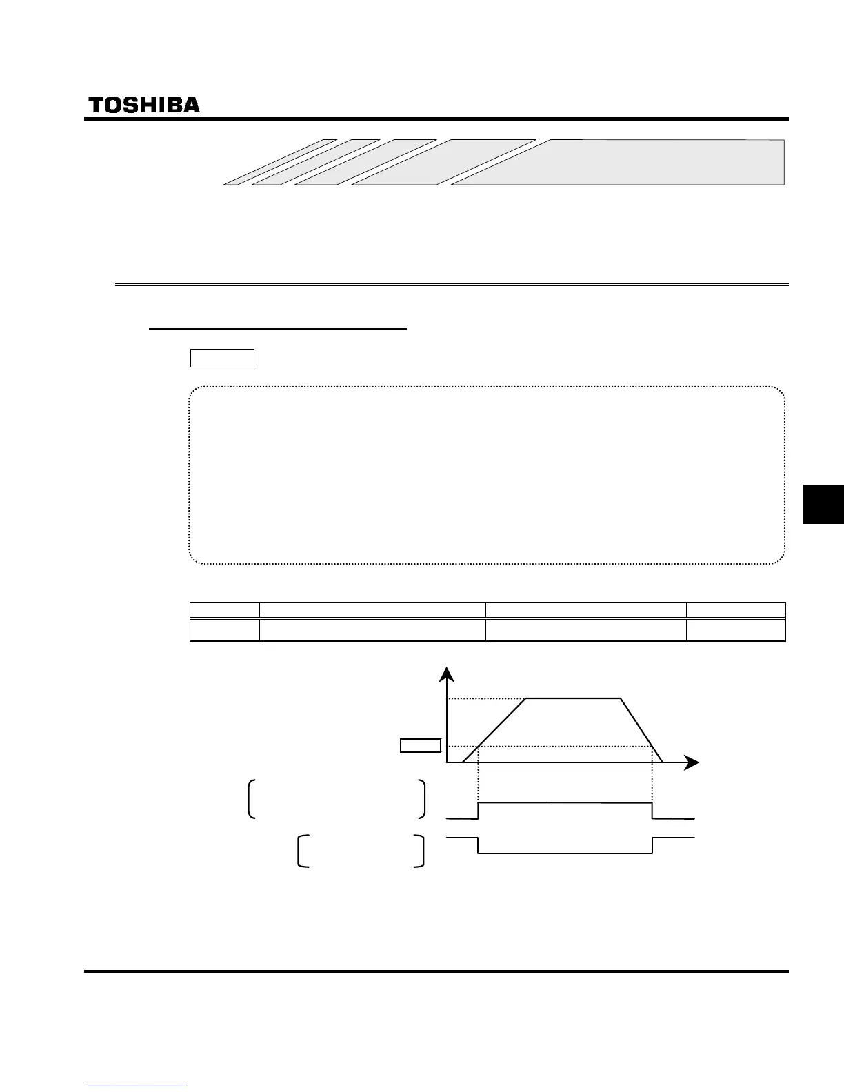
6.1.1 Low-speed signal
H : Low-speed signal output frequency
• Function
When the output frequency exceeds the setting of H an ON signal will be generated. This signal
can be used as an electromagnetic brake excitation/release signal.
This signal can also be used as an operation signal when H is set to 0.01, because an ON signal
is put out if the output frequency exceeds 0.0Hz.
+ Relay output (250Vac-1A (cosφ=1), 30Vdc-0.5A, 250Vac-0.5A (cosφ=0.4)
at RY-RC, FLA-FLC-FLB terminals (Default setting: RY-RC).
+ If the inverter is so set, the signal will be put out through the open collector OUT and NO output
terminals (24 Vdc-Max. 50 mA).
[Parameter setting]
Title Function Adjustment range Default setting
H
Low-speed signal output frequency
0.0 ∼ HJ (Hz)
0.0
Output frequency
Time [s]
H
Low-speed signal output
RY-RC terminals (Default setting)
P24-OUT terminals
FLA-FLC-FLB terminals
ON
OFF
Low-speed signal output:
Inverted
ON
OFF
[Hz]
0
Set frequency

 Loading...


