E6581158
J-3
10
10.2 Installation of a magnetic contactor
If using the inverter without installing a magnetic contactor (MC) in the primary circuit, use an MCCB (with a
power cutoff device) to open the primary circuit when the inverter protective circuit is activated.
If using a braking resistor or braking resistor unit, install a magnetic contactor (MC) or non-fuse circuit breaker
with a power cutoff device to the power supply of the inverter, so that the power circuit opens when the failure
detection relay (FL) in the inverter or the external overload relay is activated.
Q Magnetic contactor in the primary circuit
To detach the inverter from the power supply in any of the following cases, insert a magnetic contactor (pri-
mary-side magnetic contactor) between the inverter and the power supply.
(1) If the motor overload relay is tripped
(2) If the protective detector (FL) built into the inverter is activated
(3) In the event of a power failure (for prevention of auto-restart)
(4) If the resistor protective relay is tripped when a braking resistor or braking resistor unit is used
When using the inverter with no magnetic contactor (MC) on the primary side, install a non-fuse circuit
breaker with a voltage tripping coil instead of an MC and adjust the circuit breaker so that it will be tripped if
the protective relay referred to above is activated. To detect a power failure, use an undervoltage relay or
the like.
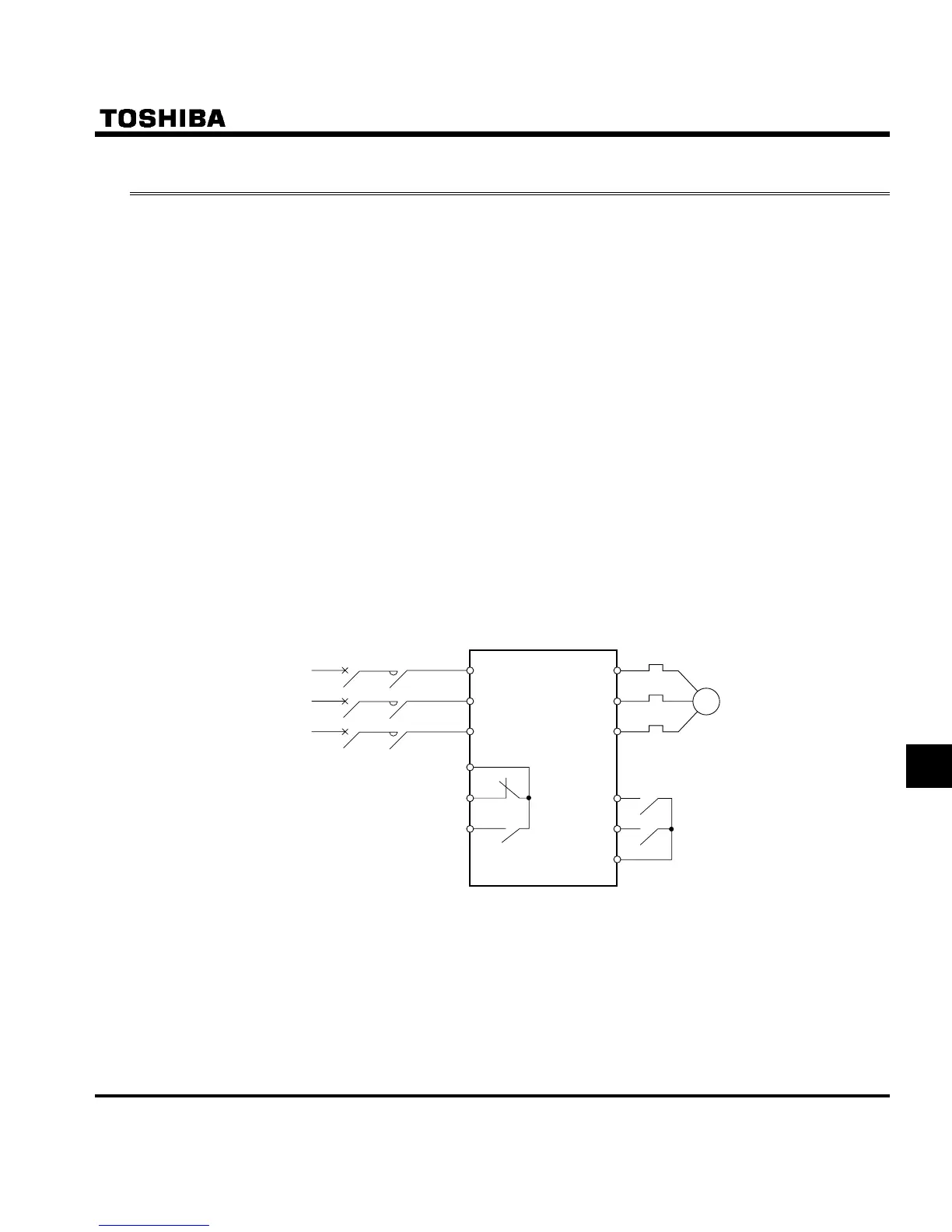
MC
VF-S11
Thermal relay
R/L1 U/T1
W/T2
W/T3
F
R
CC
S/L2
T/L3
FLC
Forward run
Reverse run
Motor
FLB
FLA
MCCB
Power supply
Example of connection of a magnetic contactor in the primary circuit
Notes on wiring
• When frequently switching between start and stop, do not use the magnetic contactor on the primary side as
an on-off switch for the inverter.
Instead, stop and start the inverter by using terminals F and CC (forward run) or R and CC (reverse run).
• Be sure to attach a surge killer to the exciting coil of the magnetic contactor (MC).

 Loading...


