E6581158
J-2
10
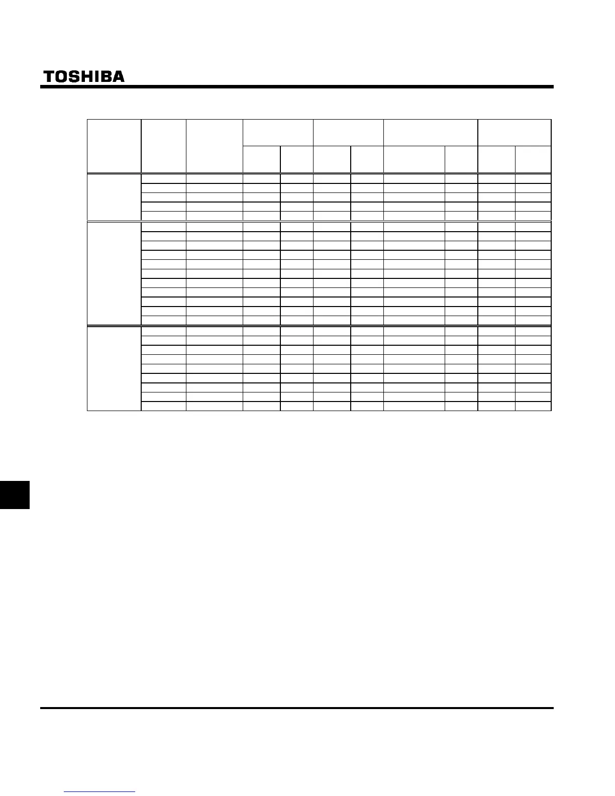
Q Selection of wiring devices
Non-fuse circuit
breaker
(MCCB) Note 4)
Magnetic contactor
(MC)
Overload relay
(THR)
Earth leakage
breaker
(ECLB)
Voltage class
Capacity of
applicable
motor
(kW)
Inverter model
Rated
current
(A)
Type
Note1)
Rated
current
(A)
Type
Note1)
Adjusted current
(A)
(For reference)
Type
Note1)
Rated
current
(A)
Type
Note1)
0.2 VFS11S-2002PL 10 NJ30N 11 LC1D096 1.3 LR3D066 10 NJV50E
0.4 VFS11S-2004PL 15 NJ30N 11 LC1D096 2.3 LR3D076 15 NJV50E
0.75 VFS11S-2007PL 20 NJ30N 11 LC1D096 3.6 LR3D086 20 NJV50E
1.5 VFS11S-2015PL 30 NJ30N 18 LC1D186 6.8 LR3D126 30 NJV50E
Single-phase
200V class
2.2 VFS11S-2022PL 40 NJ50E 35 LC1D326 9.3 LR3D146 40 NJV50E
0.2 VFS11-2002PM 5 NJ30N 11 LC1D096 1.3 LR3D066 5 NJV50E
0.4 VFS11-2004PM 5 NJ30N 11 LC1D096 2.3 LR3D076 5 NJV50E
0.55 VFS11-2005PM 10 NJ30N 11 LC1D096 2.7 LR3D086 10 NJV50E
0.75 VFS11-2007PM 10 NJ30N 11 LC1D096 3.6 LR3D086 10 NJV50E
1.5 VFS11-2015PM 15 NJ30N 11 LC1D096 6.8 LR3D126 15 NJV50E
2.2 VFS11-2022PM 20 NJ30N 13 LC1D126 9.3 LR3D146 20 NJV50E
3.7 VFS11-2037PM 30 NJ30N 26 LC1D256 15 LR3D216 30 NJV50E
5.5 VFS11-2055PM 50 NJ50E 35 LC1D326 22 LR3D226 50 NJV50E
7.5 VFS11-2075PM 60 NJ100F 50 C50J 28 LR3D326 60 NJV60F
11 VFS11-2110PM 100 NJ100F 65 C65J 44 T65J 100
NJV100F
Three-phase
200V class
15 VFS11-2150PM 125 NJ225F 80 C80A 57 T65J 125
NJV225F
0.4 VFS11-4004PL 5 NJ30N 9 LC1D096 1.0 LR3D066 5 NJV50E
0.75 VFS11-4007PL 5 NJ30N 9 LC1D096 1.6 LR3D076 5 NJV50E
1.5 VFS11-4015PL 10 NJ30N 9 LC1D096 3.6 LR3D086 10 NJV50E
2.2 VFS11-4022PL 15 NJ30N 9 LC1D096 5.0 LR3D106 15 NJV50E
3.7 VFS11-4037PL 20 NJ30N 13 LC1D126 6.8 LR3D126 20 NJV50E
5.5 VFS11-4055PL 30 NJ30N 17 LC1D186 11 LR3D166 30 NJV50E
7.5 VFS11-4075PL 30 NJ30N 25 LC1D256 15 LR3D216 30 NJV50E
11 VFS11-4110PL 50 NJ50E 33 LC1D326 22 LR3D226 50 NJV50E
Three-phase
400V class
(Note 5)
15 VFS11-4150PL 60 NJ100F 48 C50J 28 LR3D326 60
NJV100F
Note 1: Produced by Schneider Toshiba electric corporation.
Note 2: Be sure to attach a surge killer to the exciting coil of the relay and the magnetic contactor.
Note 3: When using the auxiliary contacts 2a of the magnetic contactor MC for the control circuit, connect the
contacts 2a in parallel to increase reliability.
Note 4: Select an MCCB with a current breaking rating appropriate to the capacity of the power supply, because
short-circuit currents vary greatly depending on the capacity of the power supply and the condition of the
wiring system. The MCCB, MC, THR and ECLM in this table were selected, on the assumption that a
power supply with a normal capacity would be used.
Note 5: 400V class: For the operation and control circuits, regulate the voltage at 200V or less with a step-down
transformer.

 Loading...


