E6581158
B-6
2
2.3 Description of terminals
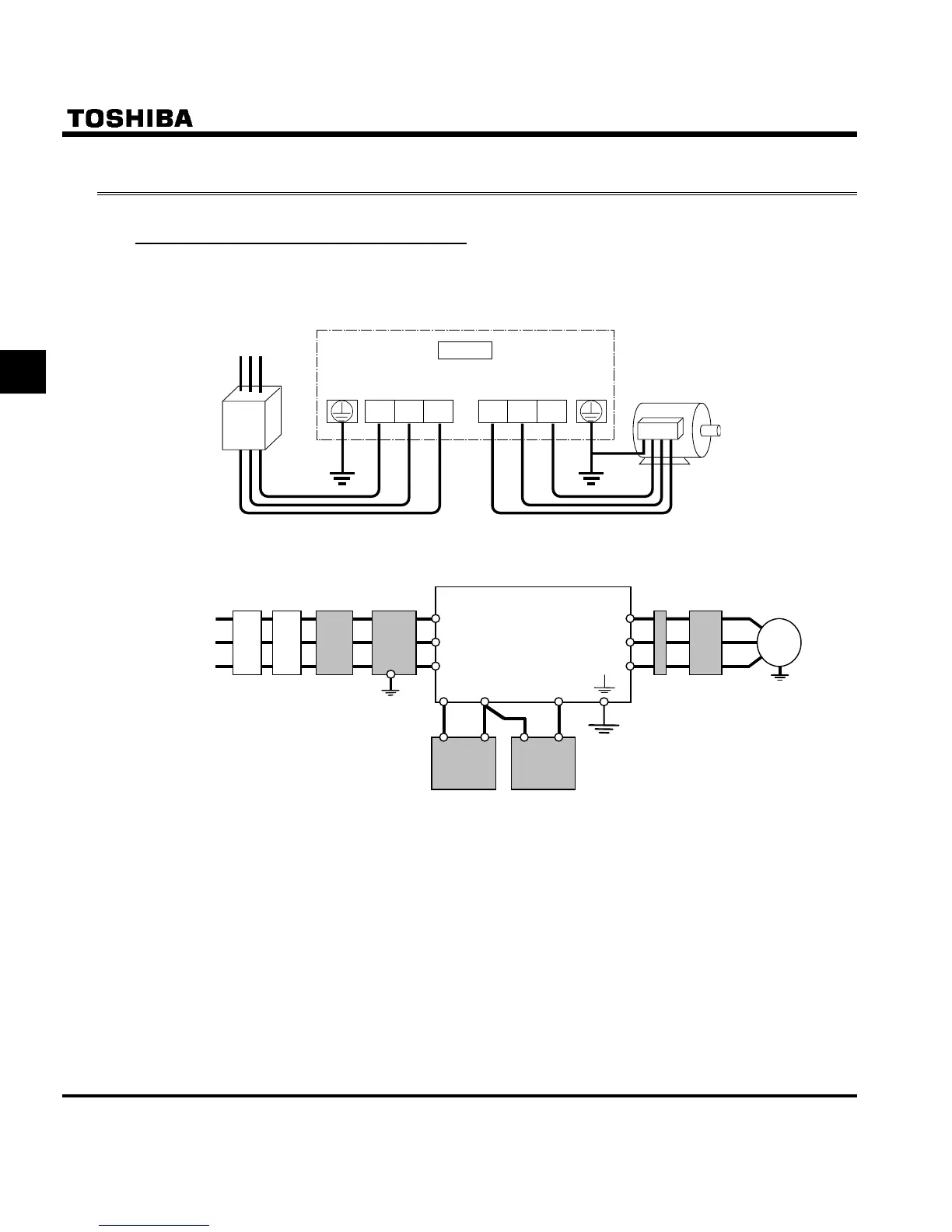
2.3.1 Main circuit terminals
This diagram shows an example of wiring of the main circuit. Use options if necessary.
Q Power supply and motor connections
VF-S11
Power supply
E
R/L1 S/L2 T/L3 U/T1 V/T2 W/T3
Motor
Power lines are
connected to R., S., and T.
Motor lines are
connected to U., C., and W.
No-fuse breaker
Q Connections with peripheral equipment
Motor
Power
supply
Inverter
DC reactor
Surge suppression
filter
Braking resistor
No-fuse
braker
R/L1
/L2
T/L3
PB PA/+
PO
V/T2
U/T1
W/T3
IM
Magnetic
connector
Input AC
reactor
noise reduction
filter (Soon to be
released)
Zero-phase
reactor
Note: The T/L3 terminal is not provided for any single-phase 200V model. So if you are using a single-phase
200V model, use the R/L1 and S/L2 terminals to connect power cables.

 Loading...


