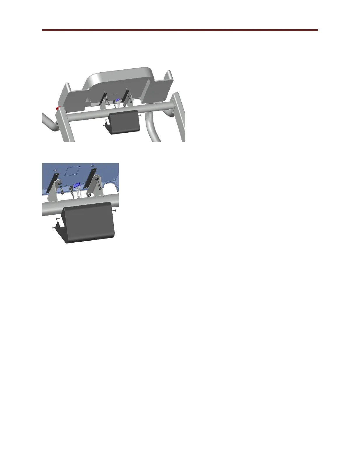
4. Figure 5-2 shows the mounting
components included with the
shipment of the treadmill. The kit
contains:
(4) ¼-20 bolts
(1) Black cover
(4) #10-32 Screws
(2) Rubber isolators
(4) Washers
5. Connect electrical 6 pin connection
to J8 and quick disconnect to BC4
and BC5 to the back of the LCD
Screen console from the connectors
within the handrail cross brace.
6. Attach the console to the console
supports with the hardware supplied
in the order shown in Figure 5-3.
Ensure the rubber pads are placed
between the steel mounting surface
and the back of the console. Tighten
bolts evenly.
7. Position the black cover and align
the holes in the side of the mount
with those in the cover. Secure cover
with (4) #10-32 screws.