76
●
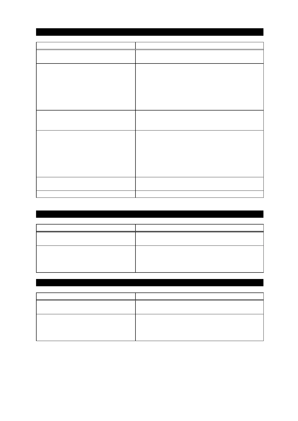
Digital output cannot be read.
Erroneous wiring or broken wire of
the EXT-I/O connector.
Correct the wiring and check continuity using a
circuit tester. (See page12.)
Erroneous wiring or broken wire of
the EXT-
wiring.
Common setting before shipment is pin 5. Each
digital output signal is turned ON/OFF between
common electrodes.
Connect output common to pin 5, or change
common setting or connect GND and pin 5 in
connector by means of a jumper wire. (See
No voltage is outputted if output
signal is not connected by pull-up
Voltage cannot be read with the type that does
not use the pull-up method.
Polarity of electrode to be connected is
incorrect.
When relay contact input unit is used, it is often
the case that one side is connected to the power
supply. In this case, connect the common side
of the gauge to the minus side of the power
supply and each signal to the plus side. If an
inverse voltage is applied, the internal element
Line voltage connected is not correct.
100VAC power is connected to some units. In
this case, the internal element will fail.
Failure of output circuit
Contact ULVAC for inspection and repair.
●
Display and analog output differ.
Incorrect recorder output mode is
selected.
Set a correct mode.(See page41.)
Recorder output is shifted as a whole.
The recorder output may shift for a potential
difference if it exists between GND on the signal
reading side and GND of the vacuum gauge.
Improve GND or add an isolation amplifier.
●
Dispay and BCD output differ.
Erroneous wiring or broken wire of
the EXT-I/O connector.
Correct the wiring and check continuity using a
circuit tester. (See page 12.)
Data rewriting time has been read.
BCD output is rewritten at intervals of 100 ms.
The value is not correct during rewriting (1 ms).
Perform processing by DATA VALID signal.