4.3 Controller I/O
4.3.2.2 Connecting emergency stop buttons
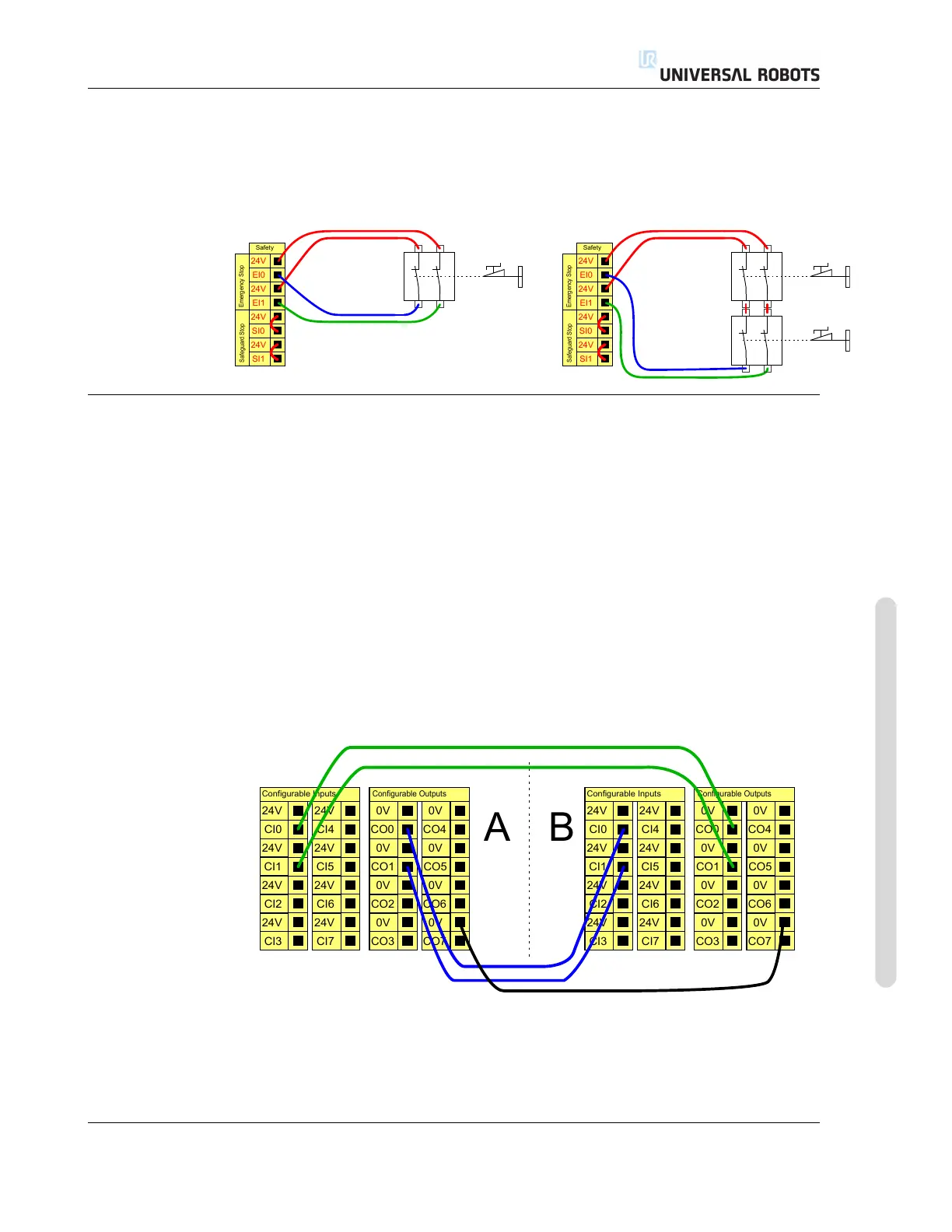
In most applications it is required to use one or more extra emergency stop buttons.
The illustration below show how one or more emergency stop buttons.
24V
EI1
24V
SI0
24V
SI1
24V
EI0
Safety
Safeguard Stop
Emergency Stop
24V
EI1
24V
SI0
24V
SI1
24V
EI0
Safety
Safeguard Stop
Emergency Stop
4.3.2.3 Sharing emergency stop with other machines
It is often desired to set up a common emergency stop circuit when the robot is used
together with other machines. By doing so, the operator does not need to think about
which emergency stop buttons to use.
The normal emergency stop input cannot be used for sharing purposes, since both
machines will wait for the each other to go out of the emergency stopped condition.
In order to share the emergency stop function with other machinery, the following
configurable I/O functions must be configured through the GUI.
• Configurable input pair: External emergency stop.
• Configurable output pair: System emergency stop.
The illustration below shows how two UR robots share their emergency stop func-
tions. In this example the configured I/Os used are “CI0-CI1” and “CO0-CO1”.
24V
CI1
24V
CI2
24V
CI3
24V
CI0
Configurable Inputs
24V
CI5
24V
CI6
24V
CI7
24V
CI4
0V
CO1
0V
CO2
0V
CO3
0V
CO0
Configurable Outputs
0V
CO5
0V
CO6
0V
CO7
0V
CO4
24V
CI1
24V
CI2
24V
CI3
24V
CI0
Configurable Inputs
24V
CI5
24V
CI6
24V
CI7
24V
CI4
0V
CO1
0V
CO2
0V
CO3
0V
CO0
Configurable Outputs
0V
CO5
0V
CO6
0V
CO7
0V
CO4
A
B
If more than two UR robot or other machines needs to be connected, a safety PLC is
needed to control the emergency stop signals.
Version 3.1 (rev. 17782)
Copyright © 2009-2015 by Universal Robots A/S. All rights reserved.
I-25 UR5/CB3