13.12 Installation → Features
Move robot here
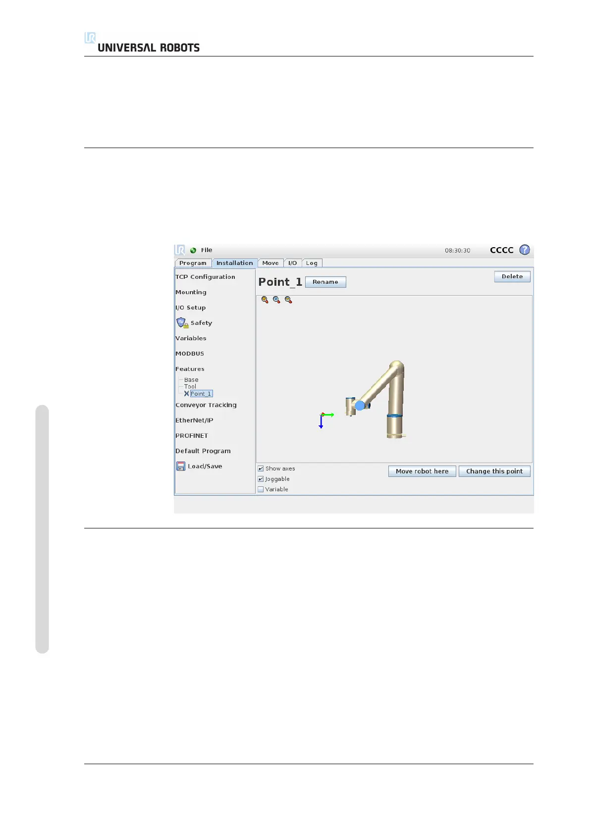
Pressing this button will move the robot arm towards the selected feature. At the
end of this movement, the coordinate systems of the feature and the TCP will coin-
cide.
13.12.2 New Point
Push this button to add a point feature to the installation. The point feature is
typically chosen when defining a safety boundary or a global home configuration of
the robot arm. The pose of a point feature is defined as the position and orientation
of the TCP at that point.
13.12.3 New Line
Push this button to add a line feature to the installation. The line feature is typically
chosen to define lines that the robot need to follow, e.g. when using conveyor
tracking. A line l is defined as an axis between two point features p1 and p2 as
shown in figure 13.3.
This axis, directed from the first point towards the second point, will constitute the
y-axis of the line coordinate system. The z-axis will be defined by the projection of
the z-axis of p1 onto the plane perpendicular to the line. The position of the line
coordinate system is the same as the position of p1.
CB3 II-54 Version 3.4.5
Copyright © 2009–2017 by Universal Robots A/S. All rights reserved.