13.4 AutoMove Tab
name. Configurable outputs that are reserved for safety settings are not togglable
and will be displaed as LED’s only.
The electrical details of the signals are described in chapter 5.3.
Analog Domain Settings The analog I/O’s can be set to either current [4-20mA]
or voltage [0-10V] output. The settings will be remembered for eventual later
restarts of the robot controller when a program is saved.
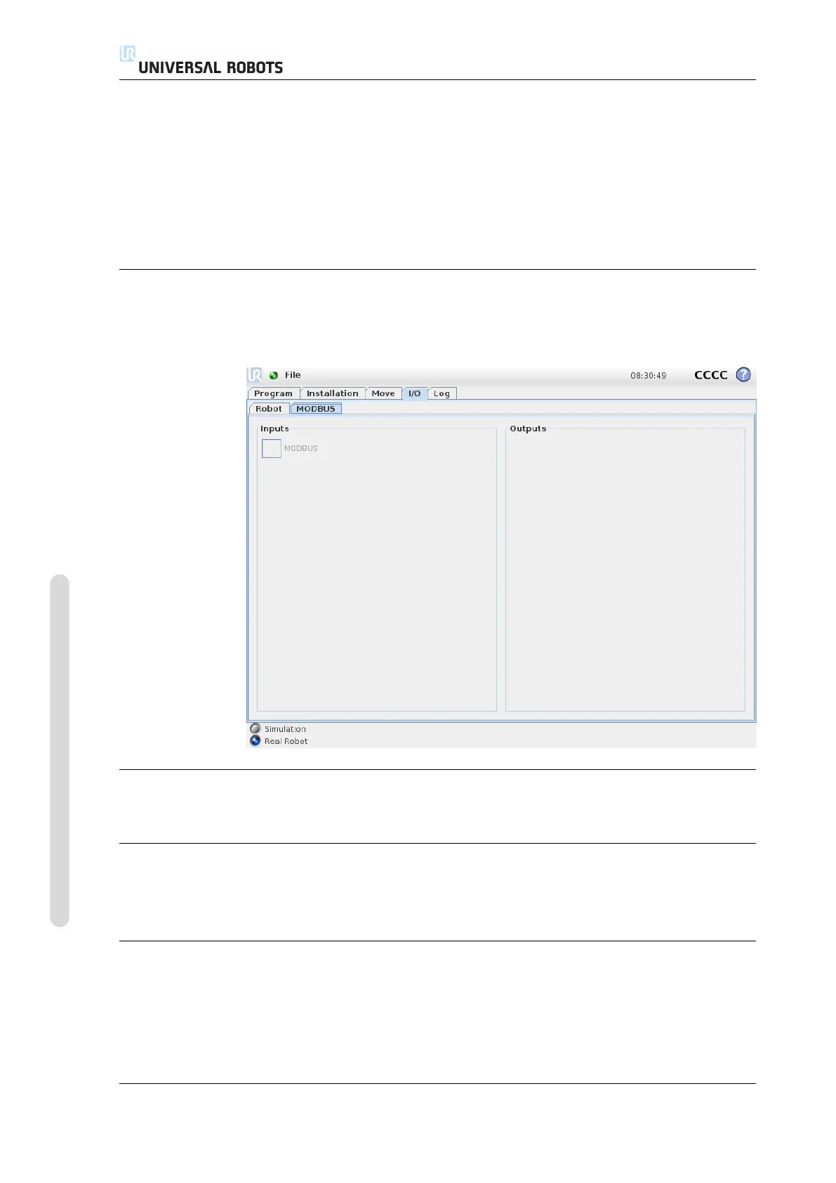
13.3 MODBUS client I/O
Here, the digital MODBUS client I/O signals as set up in the installation are shown.
If the signal connection is lost, the corresponding entry on this screen is disabled.
Inputs
View the state of digital MODBUS client inputs.
Outputs
View and toggle the state of digital MODBUS client outputs. A signal can only be
toggled if the choice for I/O tab control (described in 13.8) allows it.
13.4 AutoMove Tab
The AutoMove tab is used when the robot arm has to move to a specific position in
its workspace. Examples are when the robot arm has to move to the start position
of a program before running it, or when moving to a waypoint while modifying a
program.
CB3 II-38 Version 3.4.5
Copyright © 2009–2017 by Universal Robots A/S. All rights reserved.