2.5 Safety-related Electrical Interfaces
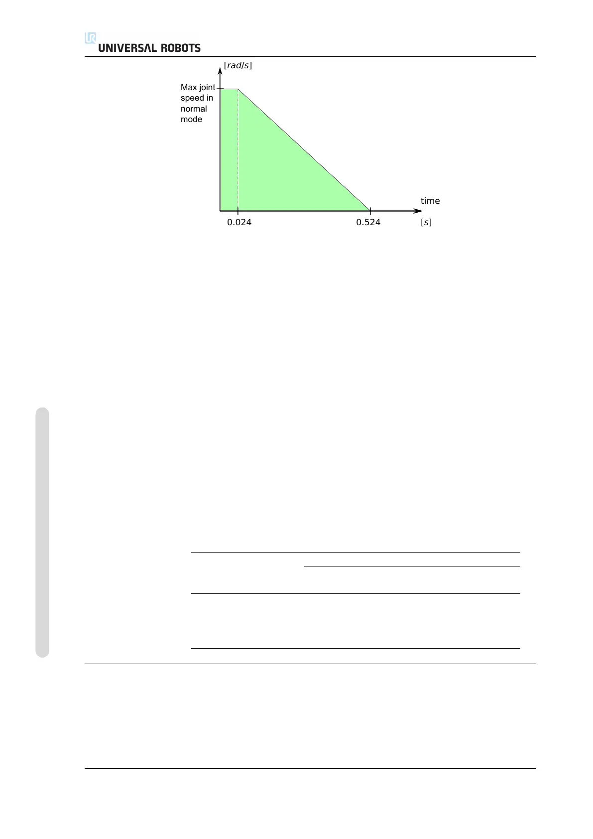
Max joint
speed in
normal
mode
[rad/s]
[s]
time
0.5240.024
Figure 2.2: The green area below the ramp is the allowed speeds for a joint during braking. At time 0 an
event (emergency stop or safeguard stop) is detected at the safety processor. Deceleration begins after
24 ms.
Safeguard Stop input, the robot arm is only allowed to start moving again after a
positive edge on the safeguard reset input occurs. If any of the above properties are
not satisfied, the safety system issues a Stop Category 0.
A transition to Reduced mode triggered by the reduced mode input is monitored as
follows:
1. The safety system accepts both Normal and Reduced mode limit sets for 500 ms
after the reduced mode input is triggered.
2. After 500 ms, only the Reduced mode limits are in effect.
If any of the above properties are not satisfied, the safety system issues a Stop Cat-
egory 0.
A Stop Category 0 is performed by the safety system with the performance de-
scribed in the following table. The worst-case reaction time is the time to stop and
to de-energize (discharge to an electrical potential below 7.3 V) a robot running at
full speed and payload.
Worst Case
Safety Input Function Detection
Time
De-energizing
Time
Reaction
Time
Robot Emergency Stop 250 ms 1000 ms 1250 ms
Emergency Stop Button 250 ms 1000 ms 1250 ms
System Emergency Stop 250 ms 1000 ms 1250 ms
Safeguard Stop 250 ms 1000 ms 1250 ms
2.5.2 Safety-related Electrical Outputs
The table below gives an overview of the safety-related electrical outputs:
UR5/CB3 I-16 Version 3.4.5
Copyright © 2009–2017 by Universal Robots A/S. All rights reserved.